5.3 Controller I/O
24V
EI1
24V
SI0
24V
SI1
24V
EI0
Safety
Safeguard Stop
Emergency Stop
24V 0V
24V
0V
DANGER:
1. The robot resumes movement automatically when the safe-
guard signal is re-established. Do not use this configuration
if signal can be re-established from the inside of the safety
perimeter.
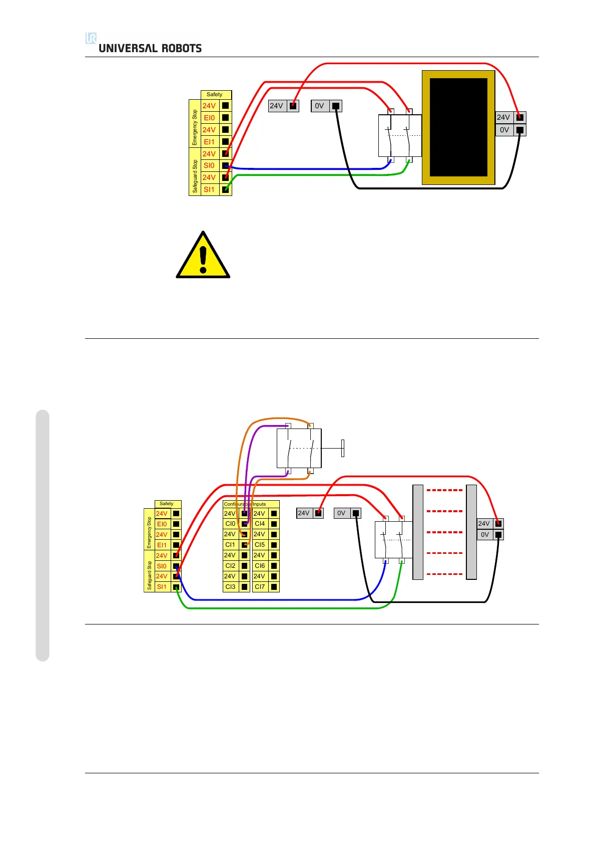
5.3.2.5 Safeguard stop with reset button
If the safeguard interface is used to interface a light curtain, a reset outside the
safety perimeter is required. The reset button must be a two channel type. In this
example the I/O configured for reset is “CI0-CI1”, see below.
24V
EI1
24V
SI0
24V
SI1
24V
EI0
Safety
Safeguard Stop
Emergency Stop
24V 0V
24V
0V
24V
CI1
24V
CI2
24V
CI3
24V
CI0
Configurable Inputs
24V
CI5
24V
CI6
24V
CI7
24V
CI4
5.3.3 General purpose digital I/O
This section describes the general purpose 24V I/O (Gray terminals) and the con-
figurable I/O (Yellow terminals with black text) when not configured as safety I/O.
The common specifications in section 5.3.1 must be observed.
The general purpose I/O can be used to drive equipment like pneumatic relays
directly or for communication with other PLC systems. All digital outputs can be
disabled automatically when program execution is stopped, see more in part II. In
this mode, the output is always low when a program is not running. Examples are
UR5/CB3 I-34 Version 3.4.5
Copyright © 2009–2017 by Universal Robots A/S. All rights reserved.