5.3 Controller I/O
shown in the following subsections. These examples use regular digital outputs
but any configurable outputs could also have be used if they are not configured to
perform a safety function.
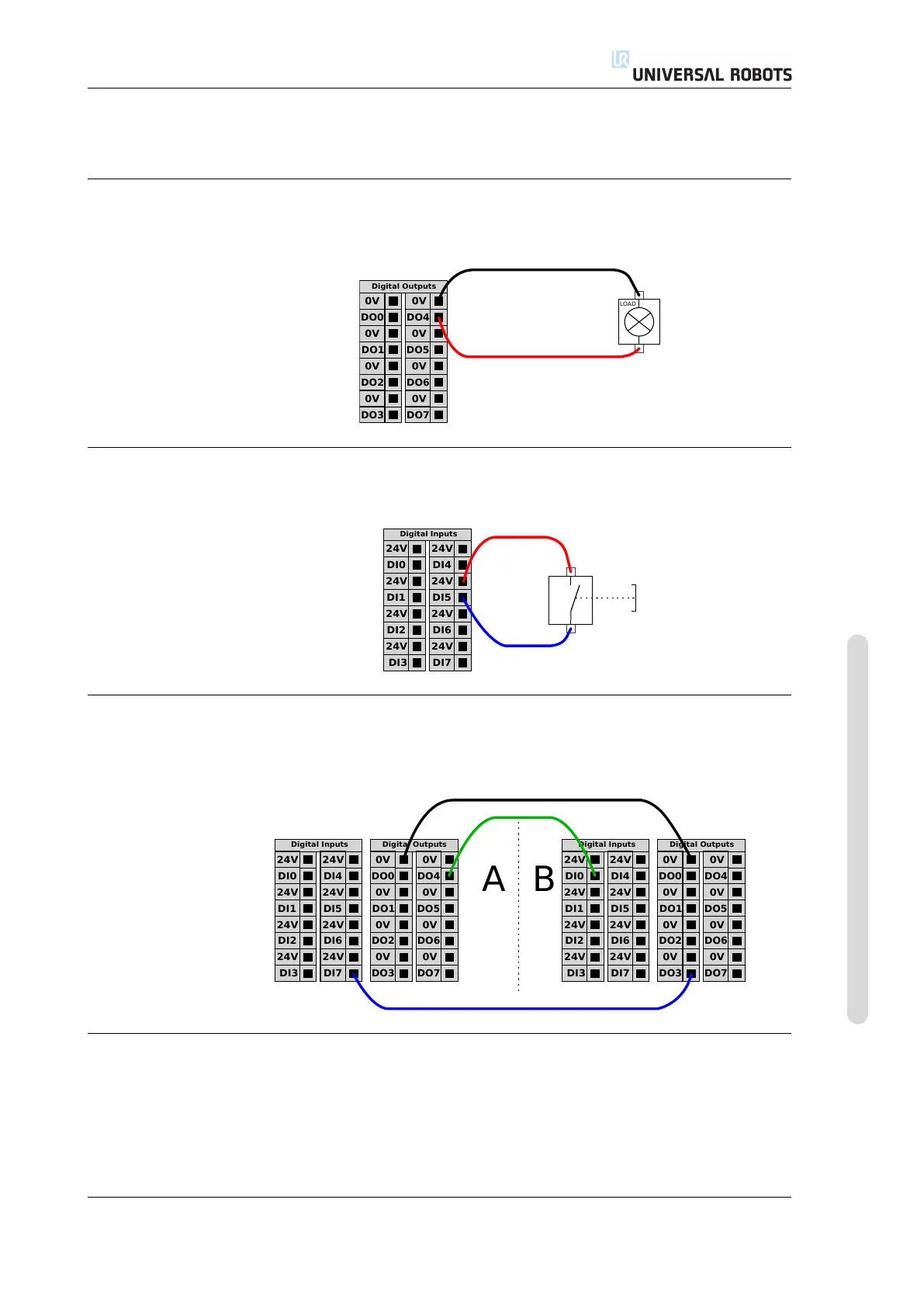
5.3.3.1 Load controlled by a digital output
This example shows how to connect a load to be controlled from a digital output,
see below.
0V
DO1
0V
DO2
0V
DO3
0V
DO0
Digital Outputs
0V
DO5
0V
DO6
0V
DO7
0V
DO4
LOAD
5.3.4 Digital input from a button
The example below shows how to connect a simple button to a digital input.
24V
DI1
24V
DI2
24V
DI3
24V
DI0
Digital Inputs
24V
DI5
24V
DI6
24V
DI7
24V
DI4
5.3.5 Communication with other machines or PLCs
The digital I/O can be used to communicate with other equipment if a common
GND (0V) is established and if the machine uses PNP technology, see below.
24V
DI1
24V
DI2
24V
DI3
24V
DI0
Digital Inputs
24V
DI5
24V
DI6
24V
DI7
24V
DI4
0V
DO1
0V
DO2
0V
DO3
0V
DO0
Digital Outputs
0V
DO5
0V
DO6
0V
DO7
0V
DO4
24V
DI1
24V
DI2
24V
DI3
24V
DI0
Digital Inputs
24V
DI5
24V
DI6
24V
DI7
24V
DI4
0V
DO1
0V
DO2
0V
DO3
0V
DO0
Digital Outputs
0V
DO5
0V
DO6
0V
DO7
0V
DO4
A B
5.3.6 General purpose analog I/O
The analog I/O interface is the green terminal. It can be used to set or measure
voltage (0-10V) or current (4-20mA) from and to other equipment.
The following is recommended to achieve the highest accuracy.
• Use the AG terminal closest to the I/O. The pair share a common mode filter.
Version 3.4.5
Copyright © 2009–2017 by Universal Robots A/S. All rights reserved.
I-35 UR5/CB3