5.3 Controller I/O
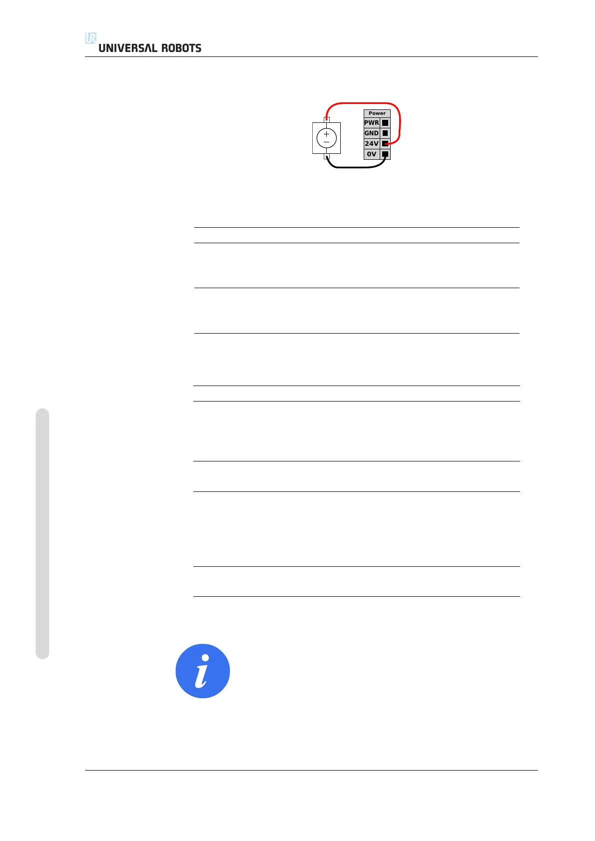
If more current is needed, an external power supply can be connected as shown
below.
The electrical specifications for both the internal and an external power supply are
shown below.
Terminals Parameter Min Typ Max Unit
Internal 24V power supply
[PWR - GND] Voltage 23 24 25 V
[PWR - GND] Current 0 - 2 A
External 24V input requirements
[24V - 0V] Voltage 20 24 29 V
[24V - 0V] Current 0 - 6 A
The digital I/O are constructed in compliance with IEC 61131-2. The electrical spec-
ifications are shown below.
Terminals Parameter Min Typ Max Unit
Digital outputs
[COx / DOx] Current* 0 - 1 A
[COx / DOx] Voltage drop 0 - 0.5 V
[COx / DOx] Leakage current 0 - 0.1 mA
[COx / DOx] Function - PNP - Type
[COx / DOx] IEC 61131-2 - 1A - Type
Digital Inputs
[EIx/SIx/CIx/DIx] Voltage -3 - 30 V
[EIx/SIx/CIx/DIx] OFF region -3 - 5 V
[EIx/SIx/CIx/DIx] ON region 11 - 30 V
[EIx/SIx/CIx/DIx] Current (11-30V) 2 - 15 mA
[EIx/SIx/CIx/DIx] Function - PNP - Type
[EIx/SIx/CIx/DIx] IEC 61131-2 - 3 - Type
Note: *For resistive loads or inductive loads of maximum 1H.
NOTE:
The word “configurable” is used for I/O that can be configured
as either safety-related I/O or normal I/O. These are the yellow
terminals with black text.
UR5/CB3 I-30 Version 3.4.5
Copyright © 2009–2017 by Universal Robots A/S. All rights reserved.