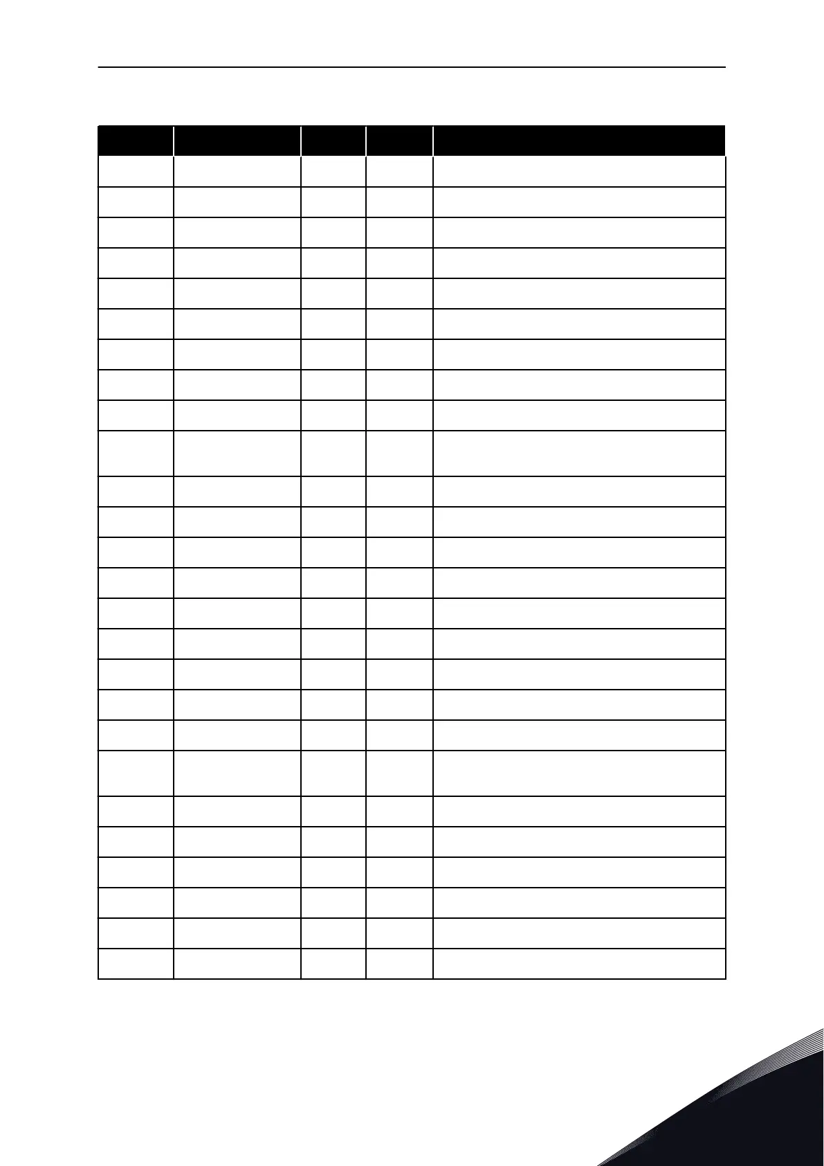
Table 44: Monitoring values, NXS drives
Index Monitoring value Unit ID Description
V1.1 Output frequency Hz 1 The output frequency to motor
V1.2 Frequency reference Hz 25 The frequency reference to motor control
V1.3 Motor speed rpm 2 The actual speed of the motor in rpm
V1.4 Motor current A 3
V1.5 Motor torque % 4 The calculated shaft torque
V1.6 Motor power % 5 The calculated motor shaft power in percentage
V1.7 Motor voltage V 6 The output voltage to motor
V1.8 DC link voltage V 7 The measured voltage in the DC-link of the drive
V1.9 Unit temperature °C 8 The heatsink temperature in Celsius or Fahrenheit
V1.10 Motor temperature % 9
The calculated motor temperature in percentage
of the nominal working temperature
V1.11 Analogue input 1 V/mA 13 AI1
V1.12 Analogue input 2 V/mA 14 AI2
V1.13 DIN 1, 2, 3 15 Shows the status of the digital inputs 1-3
V1.14 DIN 4, 5, 6 16 Shows the status of the digital inputs 4-6
V1.15 Analogue output 1 V/mA 26 AO1
V1.16 Analogue input 3 V/mA 27 AI3
V1.17 Analogue input 4 V/mA 28 AI4
V1.18 Torque reference % 18
V1.19 Sensor max temp. ºC 42 Highest measured temperature
G1.20
Multimonitoring
items
Displays three selectable monitoring values
V1.21.1 Current A 1113 Unfiltered motor current
V1.21.2 Torque % 1125 Unfiltered motor torque
V1.21.3 DC Voltage V 44 Unfiltered DC link voltage
V1.21.4 Status Word 43 SeeTable 53 Appliction Status word content.
V1.21.5 Fault History 37 Last active fault code
V1.21.6 Motor Current A 45
MULTI-PURPOSE CONTROL APPLICATION VACON · 131
24-HOUR SUPPORT +358 (0)201 212 575 · EMAIL: VACON@VACON.COM
6
 Loading...


