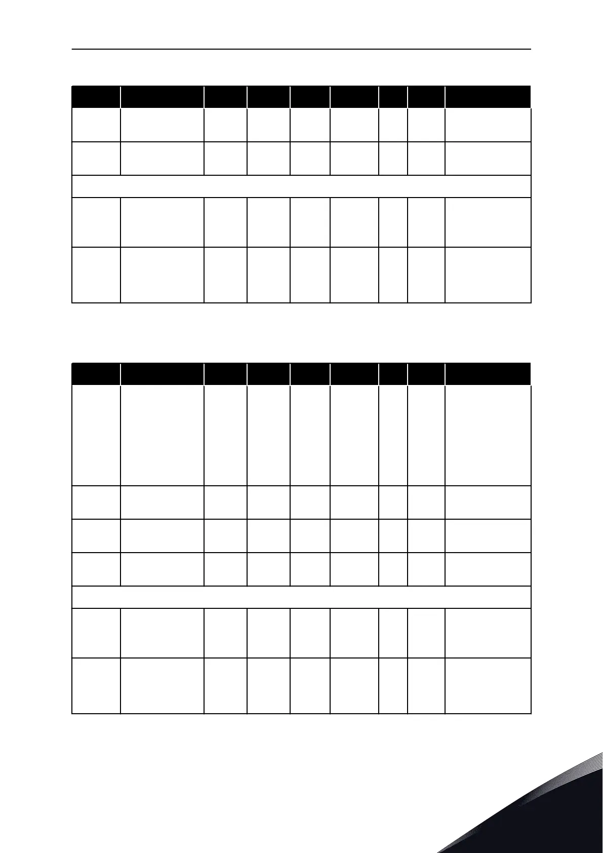
Table 62: Delayed digital output 1 (Keypad: Menu M2 -> G2.3.1)
Index Parameter Min Max Unit Default Cust ID Description
P2.3.1.3
Digital output 1 on
delay
0.00 320.00 s 0.00 487
0.00 = On delay not
in use
P2.3.1.4
Digital output 1 off
delay
0.00 320.00 s 0.00 488
0.00 = On delay not
in use
NXP drives only
P2.3.1.5 INV Delayed DO1 0 1 0 1587
0 = No
1 = Yes
P2.3.1.6 ID Bit Free DO1 0.0 200.15 0.0 1217
ID number on the
left side of the dot
and the bit number
on the right side.
* = Use TTF method to program these parameters.
Table 63: Delayed digital output 2 (Keypad: Menu M2 -> G2.3.2)
Index Parameter Min Max Unit Default Cust ID Description
P2.3.2.1
Digital output 2
signal selection
0.1 E.10 0.1 489
TTF programming
method used. See
Chapter 8.9 "Ter-
minal to function"
(TTF) programming
principle. Possible
to invert with
ID1084 (NXP only)
P2.3.2.2
Digital output 2
function
0 29 0 490
See P2.3.1.2
P2.3.2.3
Digital output 2 on
delay
0.00 320.00 s 0.00 491
0.00 = On delay not
in use
P2.3.2.4
Digital output 2 off
delay
0.00 320.00 s 0.00 492
0.00 = On delay not
in use
NXP drives only
P2.3.2.5 INV Delayed DO1 0 1 0 1588
0 = No
1 = Yes
P2.3.2.6 ID Bit Free DO1 0.0 200.15 0.0 1385
ID number on the
left side of the dot
and the bit number
on the right side.
MULTI-PURPOSE CONTROL APPLICATION VACON · 157
24-HOUR SUPPORT +358 (0)201 212 575 · EMAIL: VACON@VACON.COM
6

 Loading...


