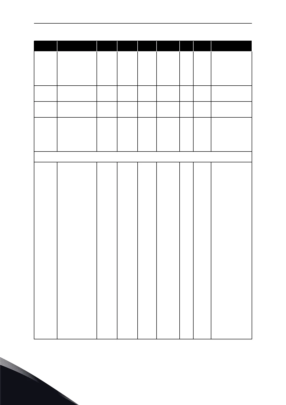
Table 78: Protections, G2.7
Index Parameter Min Max Unit Default Cust ID Description
P2.7.33 Speed error mode 0 2 0 752
0 = No response
1 = Warning
2 = Fault, stop by
coasting
P2.7.34
Speed error maxi-
mum difference
0 100 % 5 753
P2.7.35
Speed error fault
delay
0.00 100.0 s 0.50 754
P2.7.36 Safe disable mode 0 2 1 755
1 = Warning, stop
by coasting
2 = Fault, stop by
coasting
NXP and NXS drives
P2.7.37 TBoard2 Numbers 0 5 0 743
If you have a sec-
ondary tempera-
ture board instal-
led in your AC
drive you can
choose here the
number of sensors
in use. See also
the Vacon I/O
boards manual.
0 = Not used
1 = Channel 1
2 = Channel 1 & 2
3 = Channel 1 & 2
& 3
4 = Channel 2 & 3
5 = Channel 3
NOTE!
If the selected
value is greater
than the actual
number of used
sensors, the dis-
play will read
200ºC. If the input
is short-circuited
the displayed
value is –30ºC.
VACON · 184 MULTI-PURPOSE CONTROL APPLICATION
6
TEL. +358 (0)201 2121 · FAX +358 (0)201 212 205

 Loading...


