EasyManuals Logo

Vacon NX series Applications Manual

Vacon NX series
392 pages
To Next Page IconTo Next Page
To Previous Page IconTo Previous Page
Page #80 background imageLoading...
Page #80 background image
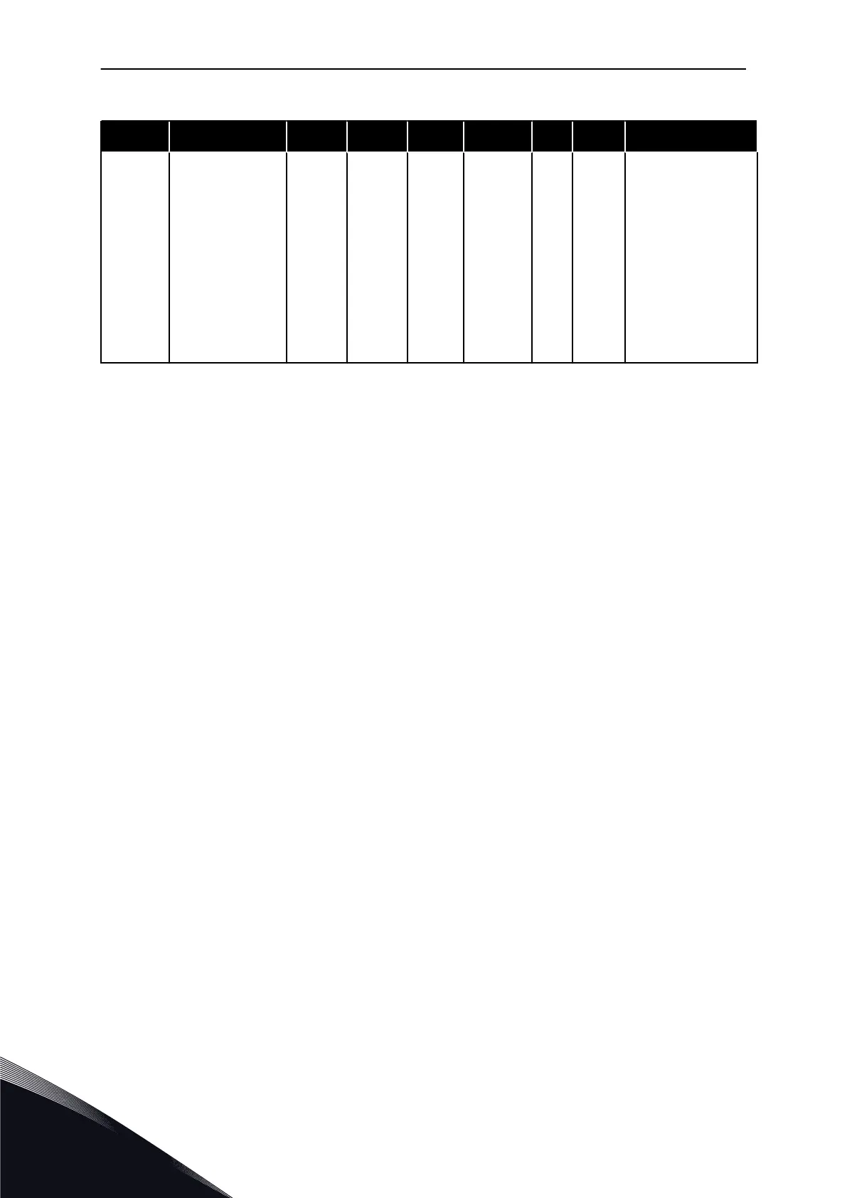
Table 26: Input signals, G2.2
Index Parameter Min Max Unit Default Cust ID Description
P2.2.18
Free analogue
input, function
0 4 0 362
0 = No function
1 = Reduces current
limit (P2.1.5)
2 = Reduces DC
braking current,
P2.4.8
3 = Reduces accel.
and decel. tmes
4 = Reduces torque
supervision limit
P2.3.15
CP = control place
cc = closing contact
oc = opening contact
** = Remember to place jumpers of block X2 accordingly. See the product's User Manual.
*** = Parameter value can only be changed after the AC drive has been stopped.
**** = Use TTF method to program these parameters.
VACON · 80 MULTI-STEP SPEED CONTROL APPLICATION
4
TEL. +358 (0)201 2121 · FAX +358 (0)201 212 205

Table of Contents

Other manuals for Vacon NX series

Questions and Answers:

Question and Answer IconNeed help?

Do you have a question about the Vacon NX series and is the answer not in the manual?

Vacon NX series Specifications

General IconGeneral
Product typeAC Drive
Output voltage range0-Uin
Frequency range0-500 Hz
Enclosure classesIP00, IP21
Mounting typesWall
Braking chopperIntegrated or external
EMC filterBuilt-in or external
Control modesScalar, Vector
Protection featuresOvercurrent, overvoltage, undervoltage, overtemperature, short circuit
Communication optionsModbus, Profibus, CANopen, Ethernet
Ambient temperature range-10°C to +50°C
Cooling methodAir-cooled

Related product manuals