Performance
Characteristics
3-4
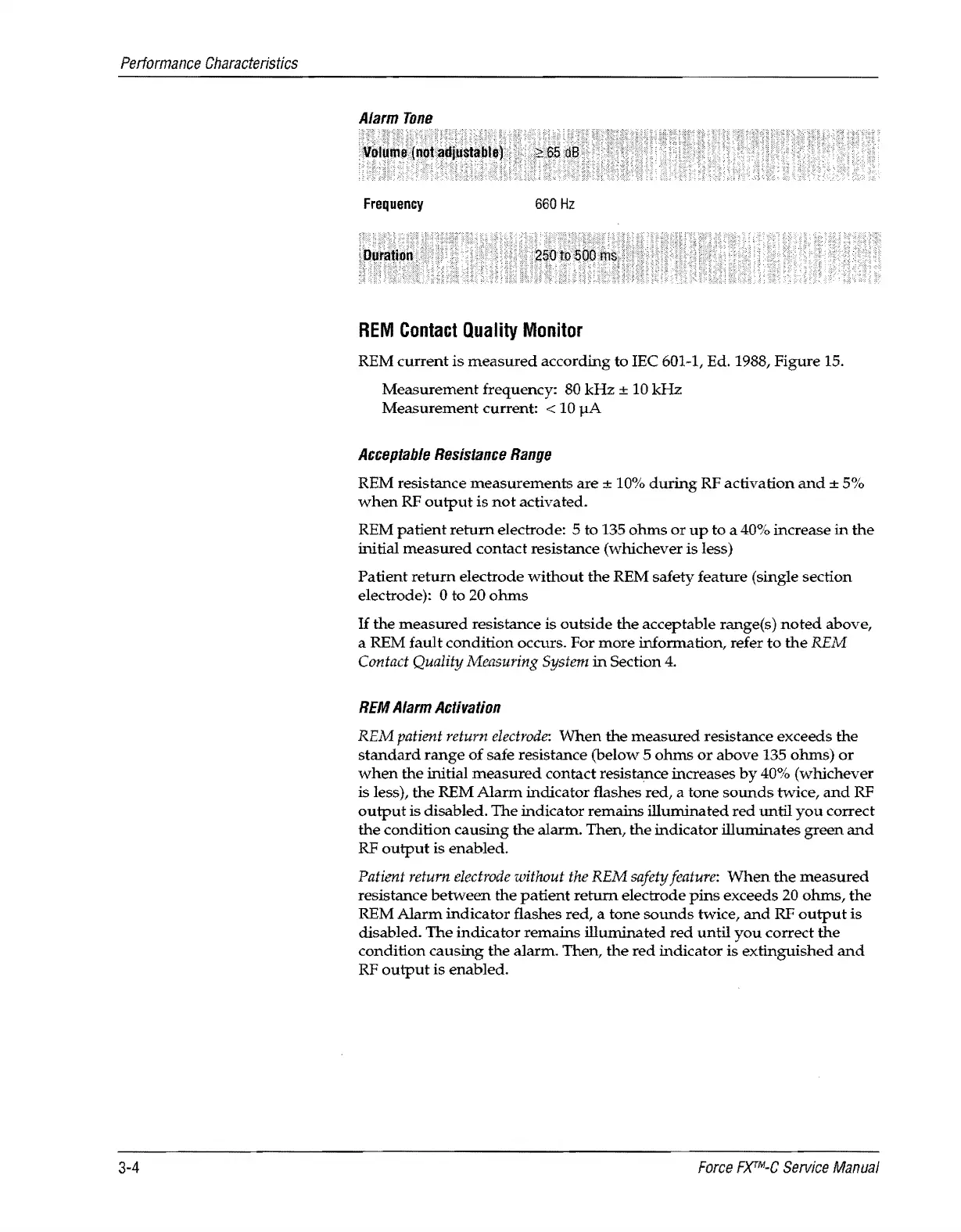
Alarm
Tone
Frequency
660
Hz
REM
Contact
Quality
Monitor
REM
current
is
measured
according to IEe 601-1, Ed. 1988,
Figure
15.
Measurement
frequency: 80
kHz
±
10
kHz
Measurement
current: < 10
pA
Acceptable
Resistance
Range
REM resistance
measurements
are
± 10%
during
RF activation
and
± 5%
when
RF
output
is
not
activated.
REM
patient
return
electrode: 5 to 135
ohms
or
up
to
a 40% increase
in
the
initial
measured
contact resistance (whichever
is
less)
Patient
return
electrode
without
the
REM safety feature (single section
electrode):
0 to 20
ohms
If
the
measured
resistance is
outside
the
acceptable range(s)
noted
above,
a REM
fault
condition
occurs.
For
more
information, refer
to
the
REM
Contact Quality Measuring
System
in
Section
4.
REM
Alarm
Activation
REM patient return
electrode:
When
the
measured
resistance exceeds
the
standard
range
of
safe resistance (below 5
ohms
or
above 135
ohms)
or
when
the
initial
measured
contact resistance increases
by
40% (whichever
is less),
the
REM
Alarm
indicator flashes red, a
tone
sounds
twice,
and
RF
output
is disabled.
The
indicator remains illuminated
red
until
you
correct
the
condition
causing
the
alarm. Then,
the
indicator illuminates
green
and
RF
output
is enabled.
Patient return
electrode
without
the
REM safety
feature:
When
the
measured
resistance
between
the
patient
return
electrode
pins
exceeds 20
ohms,
the
REM
Alarm
indicator
flashes red, a
tone
sounds
twice,
and
RF
output
is
disabled.
The
indicator
remains
illuminated
red
until
you
correct
the
condition
causing
the alarm. Then,
the
red
indicator
is
extinguished
and
RF
output
is
enabled.
Force
FXTM-C
Service
Manual