• Formats: Drop down lists for date and time format and measurement system (metric or imperial). See
Customizing the display on page62.
• Technical Support: Manufacturer's support: website, e-mail address, and telephone numbers.
• About: Information about the UPS and its software and firmware — UPS model, rating, configured capacity,
model number, and serial number.
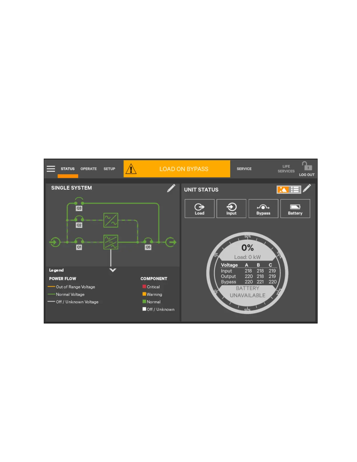
Graphic display components
The graphic display shows each configured major component of the UPS system, for both single module and multiple module
systems. The graphic display is the same for all access levels. The power path is shown by animated lines and the moving
dashes show the active power path. Breakers are shown as open or closed (see Figure 5.5 below), but are not interactive.
Components in the mimic display signify their operational status by their color, green, yellow, or red. Table 5.1 on page89
through Table 5.3 on page91 describe the various states of the indicators.
Figure 5.5 Graphic Display, Normal Operation
UNIT STATUS pane components
The UNIT STATUS pane is identical for all PIN access levels (see Figure 5.6 on the facing page). Viewers will not have the Edit
icon. In the default graphic view, the UNIT STATUS pane shows:
• Status Gauge connected load shown in kW and as a percentage of capacity; input, output, and bypass voltage for
each phase (default data may be changed. See Viewing UPS data with the status gauge on page75).
• Input Detail Icon
• Battery Detail Icon
• Bypass Detail Icon
• Load Detail Icon
58 Proprietary and Confidential ©2023 Vertiv Group Corp.
5 Operator Control and Display
Panel
Vertiv™ Liebert® APM2 30 to 120 kVA Modular UPS User Manual