Vitals Reference Manual
72 Part No. 79-MAN-04, Rev. I E.H. Wachs
Figure 5-38. Turn the adjustment screw until the A
and
B readings on the Hydraulics Test screen are
equal.
4.
When the A and B readings are equal, replace the cover
on the control box.
5.
Continue with the Hydraulics Test by tapping the RUN
button.
Using the Diagnostics Cable
To isolate possible wiring or connection issues, you can per-
form diagnostics using the optional Diagnostics Cable (part
no. 79-302-40 for the TC-100).
1.
Connect the USB end of the diagnostics cable to the
port on the TC-100.
2.
Remove the cover from the control box on the valve
operator.
3.
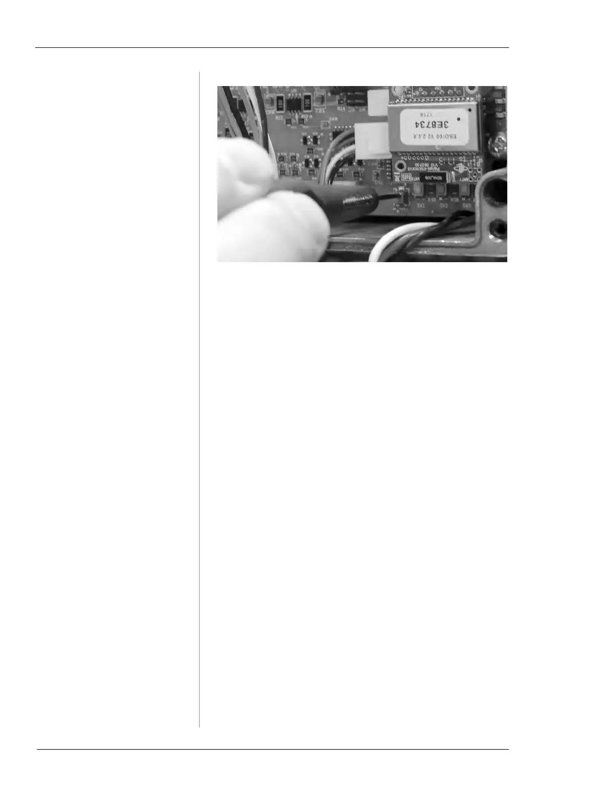
Remove the internal cable connection from the bottom
left of the circuit board, as shown in Figure 5-39.
4.
Plug the diagnostics cable into the circuit board where
you removed the internal cable.