Home
Wacker Neuson
Excavators
803
Wacker Neuson 803 Service Manual
5
of 1
of 1 rating
196 pages
Give review
Manual
Specs
To Next Page
To Next Page
To Previous Page
To Previous Page
Loading...
1-
12
SHB 803 en – Edition 2.4 * 803s110.fm
Operation
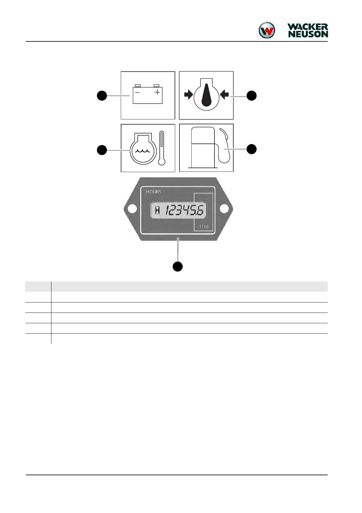
1.9
Display elements (overview)
22
20
24
21
23
Pos.
Designation
20
Indicator light (red) – al
ternator charge function
21
Indicator light (red) – engine oil pressure
22
Indicator light (red) – coolant temperature
23
Indicator light (yellow) – fuel gage
24
Hour meter
19
21
Table of Contents
Default Chapter
3
Table of Contents
3
SHB 803 en – Edition 2.4 * 803S20Ivz.fm
8
Operation
10
Information on this Service Manual
10
Identification of Warnings and Dangers
11
Designated Use and Exemption from Liability
12
Labels
13
Machine Overview (up to Serial No. AI00966)
15
Machine Overview (from Serial No. AI00967)
16
Control Stand Overview (up to Serial No. AI00814)
17
Control Stand Overview (from Serial No. AI00815)
19
Display Elements (Overview)
20
Engine Compartment Overview (up to Serial No. AI00814)
21
Engine Compartment Overview (from Serial No. AI00815)
22
Technical Data Chassis
24
Engine
24
Fuel Injection Pump
26
Engine Capacities
26
Engine Tightening Torques
26
Hydraulic System
26
Auxiliary Hydraulics Oil Flow
27
Travel Gear and Swivel Unit
27
Stabilizer Blade
27
Screwable Hose Burst Valve
27
Electrical System
28
Fuses Behind the Right-Hand Trim
28
Relays Behind the Right-Hand Trim
29
Fuses and Relays with Dual Power Option
29
Noise Levels
30
Vibration
30
Coolant Compound Table
30
Model-Specific Tightening Torques
31
General Tightening Torques
31
Tightening Torques for Hydraulic Threaded Fittings (Dry Assembly)
31
Tightening Torques for High-Resistance Threaded Fittings
33
Dimensions Model 803 (up to Serial No. AI00966)
34
Dimensions Model 803 with ROPS Rollbar (from Serial No. AI00967)
35
Dimensions Model 803 Without ROPS Rollbar (from Serial No. AI00967)
36
Lift Capacity Table 803 RD
37
Kinematics
37
Maintenance
39
Fluids and Lubricants
40
Additional Oil Change and Filter Replacement (Hydraulic System)
41
Explanation of Symbols on the Maintenance Label
43
Maintenance Label (up to Serial Number AF02412)
43
Maintenance Label (from Serial Number AF02413)
45
Maintenance Plan (Overview)
50
Service Package
50
Introduction
50
Safety-Relevant Parts
50
Fuel System
51
Specific Safety Instructions
51
Refueling
51
Stationary Fuel Pumps
52
Diesel Fuel Specification
52
Bleeding the Fuel System
53
Fuel Prefilter with Water Separator
53
Replacing the Fuel Filter
55
Engine Lubrication System
56
Checking the Oil Level
56
Adding Engine Oil
57
Changing Engine Oil
58
Replacing the Engine-Oil Filter Cartridge
59
Cooling System
60
Specific Safety Instructions
60
Checking the Coolant Level/Adding Coolant
61
Draining Coolant
63
Air Filter (up to Serial No. AI00875)
64
Replacing Air Filter Elements
65
Air Filter (from Serial No. AI00876)
65
Replacing Air Filter Elements
66
V-Belt
68
Checking V-Belt Tension
68
Retensioning the V-Belt
69
Pressure Check
70
General
70
Pressure Check of Gear Pump P2
70
Pressure Check of Gear Pump P1
71
Hydraulic System
74
Specific Safety Instructions
74
Checking the Hydraulic Oil Level
75
Adding Hydraulic Oil
76
Changing Hydraulic Oil
77
Replacing the Filter Cartridge
77
Checking Hydraulic Pressure Lines
78
Tracks
79
Checking Track Tension
79
Setting the Tracks
80
Lubrication Points on Boom (up to Serial Number AI00966)
81
Lubrication Strip
82
Overview of Lubrication Points (from Serial No. AI00967)
83
Parking the Machine
84
Lubrication Points on the Stabilizer Blade and Stabilizer Blade Cylinder
84
Lubrication Points on Swiveling Console
85
Swiveling Cylinder Lubrication Points
85
Lubrication Points on Live Ring (Ball Bearing)
86
Lubrication Points of Live Ring Teeth
87
Ball Sockets (ISO/SAE Changeover Option)
88
Maintenance of Attachments
88
Electrical System
89
Specific Safety Instructions
89
Servicing and Maintenance at Regular Intervals
89
Instructions Concerning Specific Components
90
Alternator
90
Battery
91
General Maintenance
92
Cleaning
92
General Instructions for All Areas of the Machine
92
Control Stand
92
Exterior of the Machine
93
Engine Compartment
93
Threaded Fittings and Attachments
93
Pivots and Hinges
93
Preparatory Work before Taking out of Service
94
Maintenance if the Machine Is out of Service for a Longer Period of Time
94
Putting into Operation Again
94
Engine
98
Overview of Engine 3TNV70-VNS (Tier IV Final up to 2012)
98
Fuel System
99
Checking and Adjusting Valve Clearance
101
Tightening Order for Cylinder Head Bolts
102
Checking the Injection Nozzles
103
Pressure Check
103
Checking the Nozzle Jet
103
Injection Time
104
Checking and Adjusting Injection Time
104
Replacement of Fuel Injection Pump
105
Adjusting Engine Speed
106
Compression
106
Checking the Coolant Thermostat
106
Checking the Thermal Switch
107
Oil Pressure Switch
107
Checking the Coolant Circuit
108
Engine Trouble
109
Overview of Engine 3TNV74F-SNNS (Tier IV Final from 2012)
111
Fuel System
113
Cooling System
114
Altitude-Dependent Output Reduction
115
Checking and Adjusting Valve Clearance
116
Tightening Order for Cylinder Head Bolts
118
Order for Removing the Cylinder-Head Bolts
118
Order for Installing the Cylinder-Head Bolts
118
Checking the Injection Nozzles
119
Pressure Check
119
Checking the Nozzle Jet
120
Injection Time
120
Checking Injection Time
120
Setting Injection Time
122
Removing and Installing the Injection Pump
123
Removing the Injection Pump
123
Fitting the Fuel Injection Pump
124
Measuring and Adjusting the Engine Speed
126
Compression
126
Checking the Coolant Thermostat
127
Checking the Temperature Sensor
127
Oil Pressure Switch
128
Checking the Coolant Circuit
128
Cleaning the Cooling Water Channels
128
Coolant and Fuel Hoses
129
Crankcase Vent
129
Replacing the Glow Plugs
129
Engine Trouble
130
Hydraulic System
133
Hydraulic Pump PGP505B0050CA1H2NJ7J5C-505A00 (Tier IV Final up to 2012)
134
Pump Unit: Exploded View
135
Hydraulic Pump PGP505B0040CA1H2NJ7J5C-505A0040XB1J5B1B1 (Tier IV Final from 2012)
136
Pump Unit: Exploded View
137
Main Valve Block
138
Connections
138
Legend
139
Main Valve Block Diagram
140
Pressure Limiting Valves
141
Pump Assignment
142
Traveling Drive
143
Function
144
Swivel Unit
146
Swivel Unit
147
Swivel Joint
148
Sealing
148
Mechanical Control
149
Control Levers (up to Serial No. AI00814)
149
Drive Levers (up to Serial No. AI00814)
150
Control Levers (from Serial Number AI00815)
151
Drive Levers (from Serial Number AI00815)
152
Lock Lever (from Serial Number AI00815)
153
Troubleshooting in the Hydraulic System
154
Plastic Trims
154
Electrical System
161
Ohm's Law (Current, Voltage, Resistance); Power
162
Measuring Equipment, Measuring Methods
162
Cable Color Coding
163
Relays
163
Use, Mode of Function
163
Electrical System
164
Fuses Behind the Right-Hand Trim
164
Relays Behind the Right-Hand Trim
165
Fuses and Relays with Dual Power Option
165
Control Lever Push Button
166
Working Light
166
Dynamo
167
Rectifier
167
Starter
167
Options
186
Rollbar
186
TOPS Rollbar up to Serial Number AF01416
186
Lowerable ROPS Rollbar (from Serial No. AF01417 to Serial No. AI00966)
187
Raising/Lowering the Rollbar
187
Lowering and Raising the Rollbar
188
Lowerable ROPS Rollbar from Serial No. AI00967
188
Raising/Lowering the Rollbar
189
ISO/SAE Changeover (Option)
190
Traveling Signal (Option)
191
Telematic
192
Connections
192
Functional Check/Diode
192
Zero-Emission Dual Power Drive
193
Overview
193
Other manuals for Wacker Neuson 803
Operator's Manual
228 pages
5
Based on 1 rating
Ask a question
Give review
Questions and Answers:
Need help?
Do you have a question about the Wacker Neuson 803 and is the answer not in the manual?
Ask a question
Wacker Neuson 803 Specifications
General
Brand
Wacker Neuson
Model
803
Category
Excavators
Language
English
Related product manuals
Wacker Neuson 8003 2
29 pages
Wacker Neuson EZ17
256 pages
Wacker Neuson EZ38
254 pages
Wacker Neuson ET18
298 pages
Wacker Neuson 1404
188 pages
Wacker Neuson ET35
302 pages
Wacker Neuson EZ36
302 pages
Wacker Neuson ET20
298 pages
Wacker Neuson DW60
228 pages
Wacker Neuson 3503
280 pages
Wacker Neuson 50Z3
292 pages
Wacker Neuson E16-02
302 pages