7-8 SHB 803 en – Edition 2.4 * 803s710.fm
Options
7.4 Telematic
After installing the Telematic system, module A is enabled and sends data to the Telem-
atic web portal.
Technical data
• This works in 90 countries with currently 160 roaming partners with a GPRS data
network.
• The GPS receiver registers the movements and has a low power consumption.
• Backup battery for additional safety with an autonomy time of 48 – 96 hours.
• Supplies additional information via the web-based Wacker Neuson Telematic software.
• Module has 3 digital inputs and one digital output of which 2 digital inputs (engine and
starter) are assigned at the factory. One input and output is freely assignable with other
functions, such as for monitoring an additional heating system or particulate-soot filter
or controlling these functions via SMS.
• Certified according to IP67.
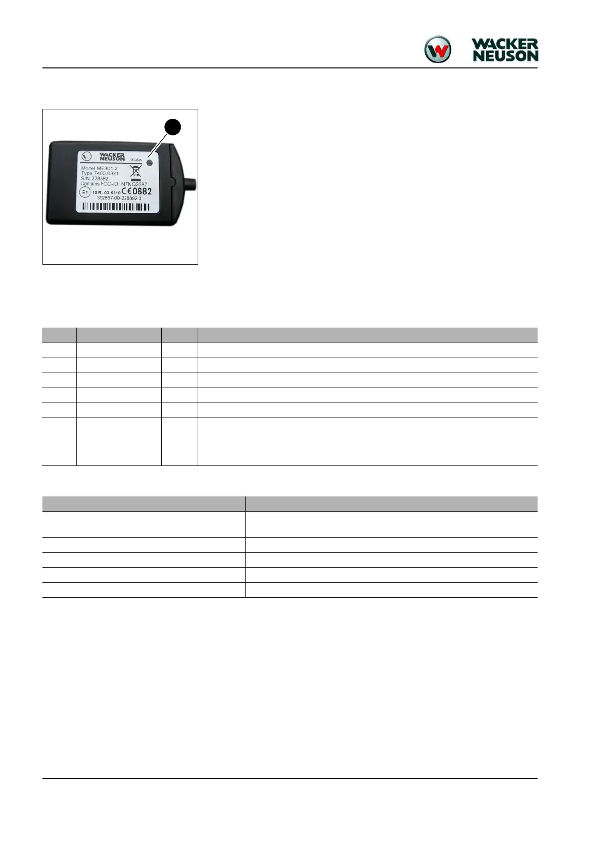
Connections
Functional check/diode
Pos. Connection Color Designation
1
Power supply rd 12 V permanent plus via a series-connected 1 ampere high-speed fuse
2
Ground bl -
3
Digital input 1 wh Engine START/STOP signal
4
Digital input 2 bn Starter ON/OFF signal
5
Digital input 4 pk Not assigned at the factory. Can be used for determining an operating state.
6
Digital output 1 ye
The digital output of the module can be used for enabling/disabling additional functions via
SMS, such as an auxiliary heater.
Important: Selection is only possible for comfort functions. Remote-control of safety-relevant
functions or functions affecting handling is prohibited under all circumstances.
LED mode Operating state
Steady green light with short, red flashing interruptions
The unit is connected with the GSM network and the GPS module is navigating
> all is OK
No light The unit is not connected with a power source
Steady red light The unit is supplied with power, but is not connected with a GSM network
Short red flashing The unit is supplied with power and is connected with a GSM network
Steady green light The unit is navigating (fixed GPS satellite position)