6-2 SHB 803 en – Edition 2.4 * 803s610.fm
Electrical system
Electrical system
6 Electrical system
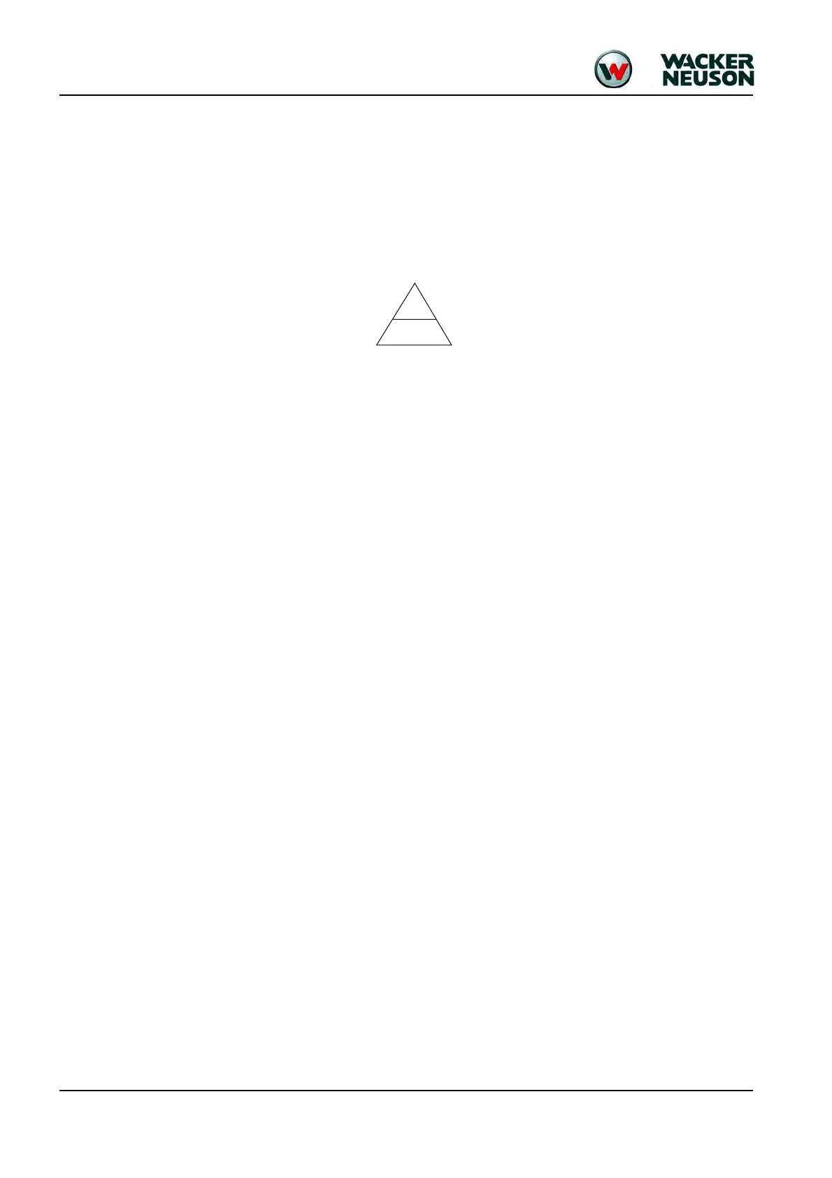
6.1 Ohm’s Law (current, voltage, resistance); power
It describes the interrelation between current, voltage and resistance.
Current “I” – Ampere (A)
Voltage “U” – Volt (V)
Resistance “R” – Ohm (
)
Mnemonic:
Output
Power “P” – Watt (W)
P = U x I = R x I² = U²/R
6.2 Measuring equipment, measuring methods
Multifunction measuring device
• Measurements of values (U, R, I, f)
• Continuity test
• Diode test
Calculate the measuring range using known data (P, U, R, I) and set before measuring!
Observe AC/DC basic setting.
➥AC = alternating current/voltage;
➥DC = direct current/voltage
Test device with acoustic and optical signal output
• Continuity test in de-energized machine electrical system and of wiring harnesses.
Measuring methods – multifunction measuring device
• Measuring current (starter switched on):
• Black cable in COM socket (ground),
• red cable in A socket or mA socket; connect in series to consumer.
• Measuring voltage (starter switched on):
• Black cable in COM socket (ground),
• red cable in V socket;
• connect in parallel to consumer.
• Measuring resistance (starter switched off):
• Black cable in COM socket (ground),
• red cable in
socket;
• connect in parallel to consumer (see measuring voltage).
Test lamp
The test lamp is used for testing lines and functions with the starter switched on.
• Line test (testing voltage):
Connect test lamp between test point (live cable) and machine ground or between test
point (grounding line) and a live cable.
• Functional check (testing current):
Connect test lamp between a connection on the consumer to be tested and the connection
line.