70 Mounting WAGO I/O System Compact
751-9301 Compact Controller 100
Manual
Version 1.1.0, valid from FW Version 03.08.07(20)
6.2.2 WAGO DIN Rails
WAGO carrier rails meet the electrical and mechanical requirements shown in the
table below.
35 × 7.5; 1 mm; steel; bluish, tinned, chromed; slotted
35 × 7.5; 1 mm; steel; bluish, tinned, chromed; unslotted
35 × 15; 1.5 mm; steel; bluish, tinned, chromed; slotted
35 × 15; 1.5 mm; steel; bluish, tinned, chromed; unslotted
35 × 15; 2.3 mm; steel; bluish, tinned, chromed; unslotted
35 × 15; 2.3 mm; copper; unslotted
35 × 8.2; 1.6 mm; aluminum; unslotted
Observe the mounting distance of the DIN rail when the load is increased!
With increased vibration and shock load, mount the DIN rail at a mounting
distance of max. 60 mm.
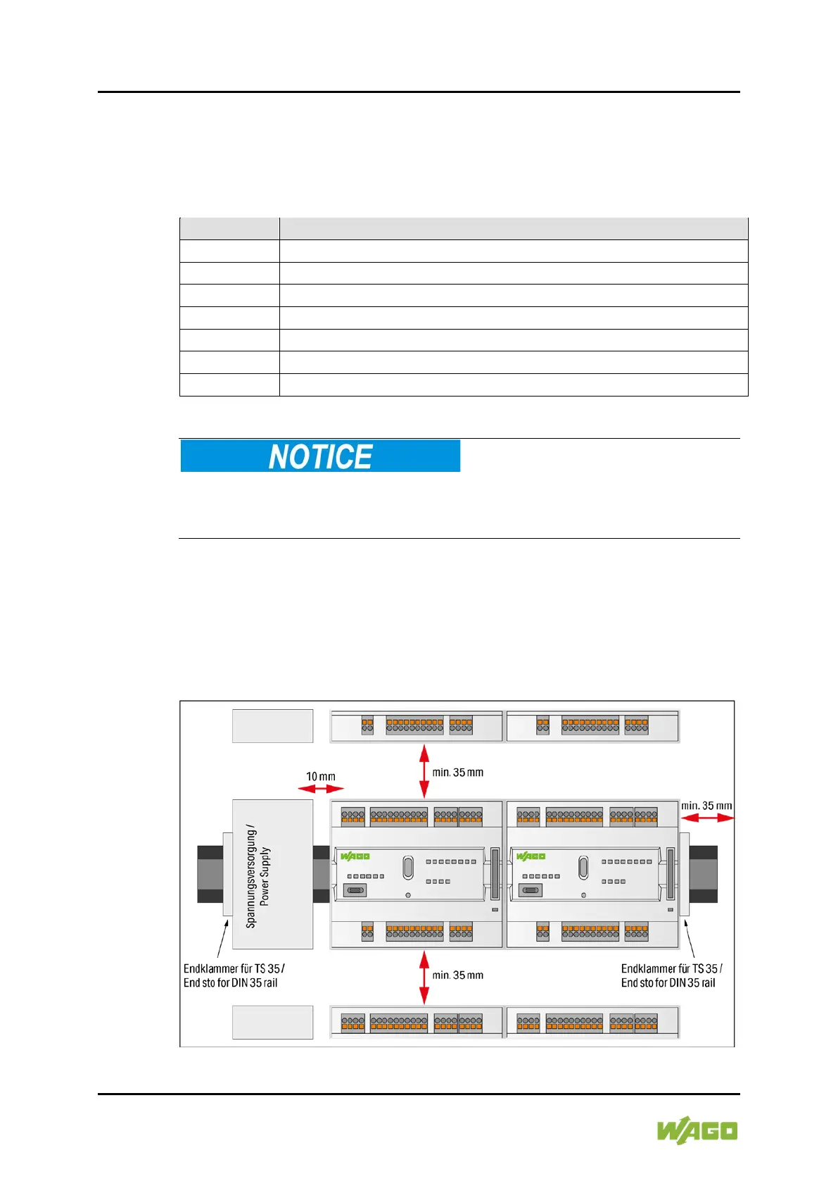
6.3 Spacing
A minimum distance of at least 35 mm to cable ducts and housing/frame
walls must be maintained for the entire fieldbus node.
For components that are adjacent on the DIN-rail, this distance can fall
below this minimum if necessary.
Figure 8: Spacing