2-10 Installing the Detector
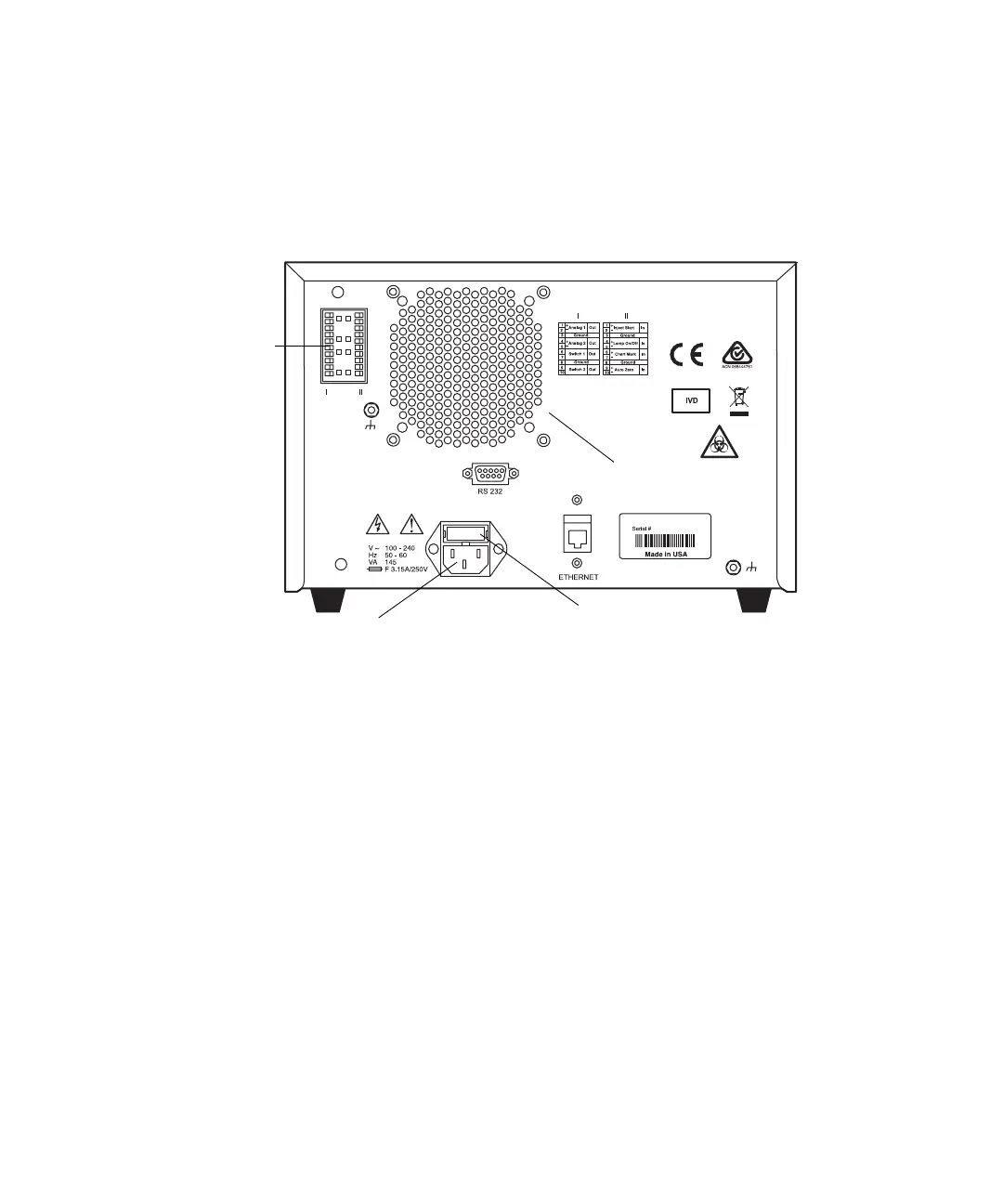
Detector rear panel
The detector connects to other Waters components through rear panel
electrical connections.
Detector rear panel electrical connections
Rear panel connections enable the following signals:
• Analog outputs – There are two pairs of attenuated analog channel
outputs with each pair supporting 2-V output to external devices or data
systems. They are labeled I and II. For input/output voltage current
specifications, see the Table titled “Operational specifications” on
page B-2.
– The 2-V output for I and II is scaled based on the AUFS (absorbance
units full scale) setting for each channel. The detector does not
provide a traditional “unattenuated” dedicated 1-V/AU output
because of its enhanced working range above 2 AU.
– The detector analog output range specifications are – 0.1 V to 2.1 V.
– You can set the AUFS value individually for the output on each
channel. Volts per AU are calculated as follows:
Volts out = Absorbance × 2V/AUFS
TP02807
Fan Vent
Fuse holder
Power input
Inputs and
Outputs