2-36 Installing the Detector
Connecting the detector to a fraction collector
The detector can trigger a fraction collector based on
• Timed events (see “Timed events” on page 3-36).
• Threshold levels (see “Threshold events” on page 3-39).
You can connect the fraction collector to one of the detector’s two
programmable switches (SW1 or SW2) and program the timed event,
threshold, or ratio at the detector front panel.
You can also connect the fraction collector to the detector to trigger a chart
mark event input each time a tube is changed at the fraction collector.
The table below indicates the correct detector-to-fraction collector and
autoinjector-to-fraction collector connections.
See also: Refer to the documentation provided with your fraction collector for
complete information.
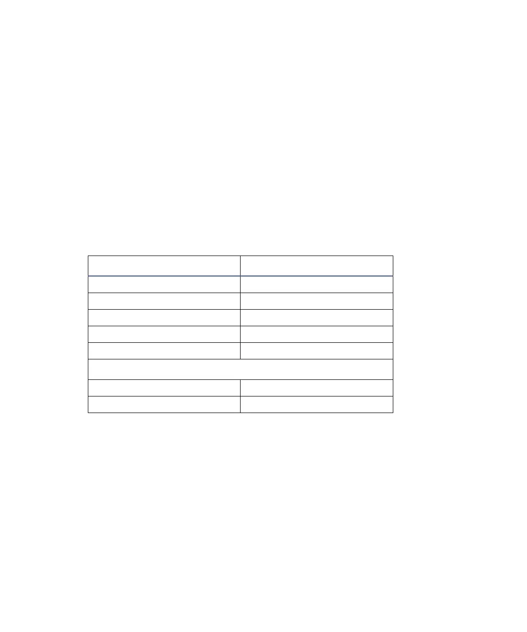
Detector connections to the fraction collector
Waters 2489 Connection Waters Fraction Collector
I Pin 3 Ground Pin 1 Detector In –
II Pin 6 Chart Mark + Pin 10 Event Marker +
II Pin 7 Chart Mark – Pin 9 Event Marker –
I Pin 6 SW1 Pin 7 External Count In +
I Pin 8 Ground Pin 8 External Count In –
Waters 2695 Separations Module/717plus Autoinjector
Inject Start + External Start In +
Inject Start – External Start In –