Controller Operation
Weber Packaging Solutions, Inc. 6-3
IDLE MODE
TAMP BLOW
DISPLAY
WINDOW
N/A
READY (GREEN)
PRINTER ENABLE
(GREEN)
N/A
LOW SUPPLY
(YELLOW)
RETURN BUTTON / STOP
INCREASE / DECREASE
BUTTONS
ARROW BUTTONS
L.E.D.s
IDLE MODE
(RED)
APPLICATOR MODE
JOG
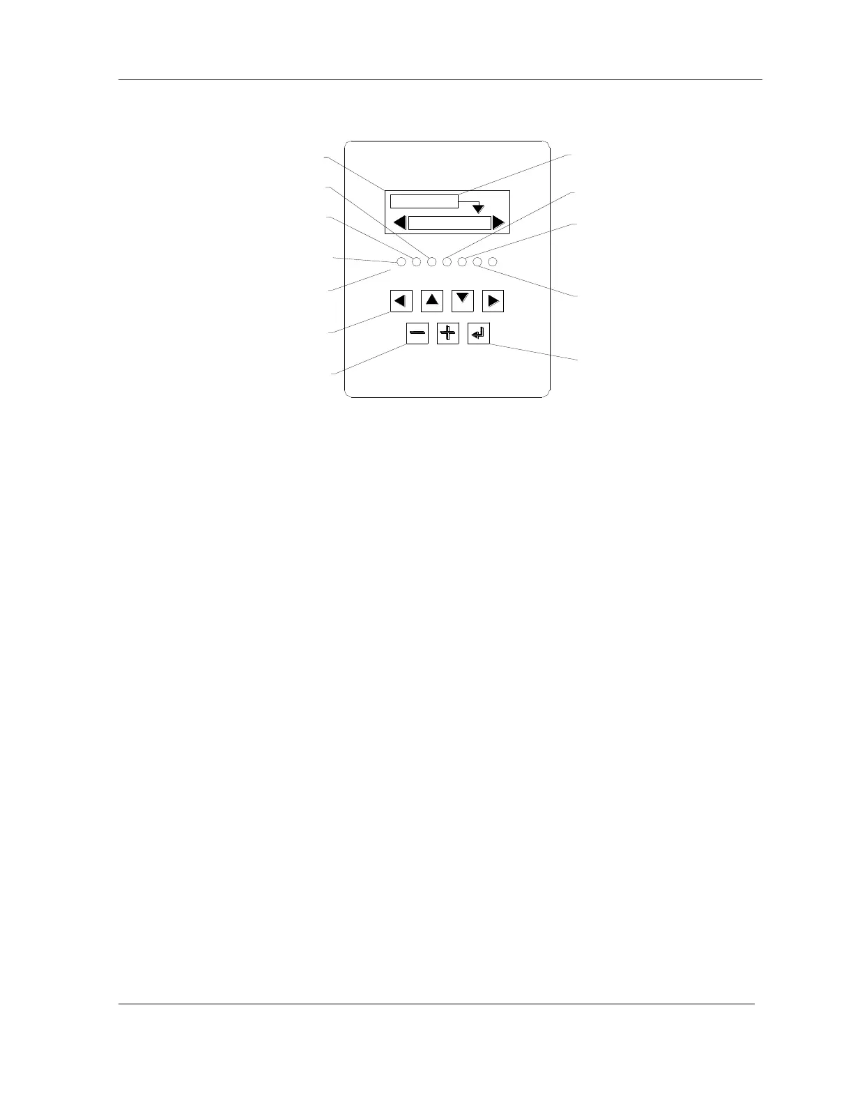
Figure 6-2: Controller Keypad
Controller Keypad
The applicator controller is located on front of the applicator (see Figure 6-2).
NOTE: The top line in the display window indicates the current mode of the applicator.
NOTE: In order for the machine to run, air must also be supplied to the machine.
The arrows in the display window indicate which arrow buttons to use to scroll through
the menus and to select the desired function. For example, in Fig 6.2, the applicator is in
Idle mode and to select Tamp Blow a user would press the [] down arrow key as
indicated by the arrow symbol extending from the Idle mode box.
The [+] and [-] buttons are used to increase or decrease numerical parameters.
The [RETURN] button returns the operator to the previous menu. Also, pressing this
button while the applicator is running will stop the cycle and allow access to the
Diagnostics or Setup screen.
The active selection is highlighted in the display window.
The LEDs light to display applicator status as follows:
RED – Error (applicator is in Idle or Error mode)
GREEN – Ready (applicator in Run mode) or Print Enable (Print start)
YELLOW – Warning (Low supply condition)
Tap the [JOG] to apply a previously printed label when the machine is in Run Mode.