7-17
E
BRKT
POWER TRIM AND TILT UNIT
2. Install the manual-valve in the body
with new O-rings.
1 O-ring (fitted into the body)
2 Manual valve seat
3 Manual release spring
(L = 6.0 mm, D = 11.5 mm)
4 Adapter 1
5 O-ring
6 Manual valve (left-handed thread)
7 Circlip
T
R
.
.
Manual valve:
3 Nm (0.3 m • kg, 2.2 ft • lb)
3. Install a new O-ring on the shuttle-pis-
ton, insert the piston into the body, then
install the main valves with new O-
rings.
1 O-ring
2 Shuttle-piston
3 O-ring
4 O-ring
5 Main valve
T
R
.
.
Main valve:
10 Nm (1.0 m • kg, 7.2 ft • lb)
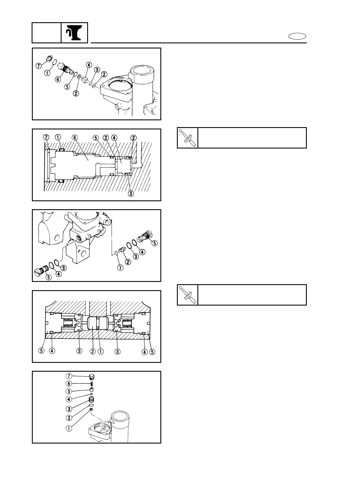
4. Install the up-relief valve with a new O-
ring and tighten the locking-bolt to the
specified torque.
1 Filter
2 O-ring
3 Up relief valve seat
4 Ball
5 Valve support pin
6 Up relief spring (L = 19.7 mm, D = 5 mm)
7 Up relief valve lock screw