8-27
–+
ELEC
E
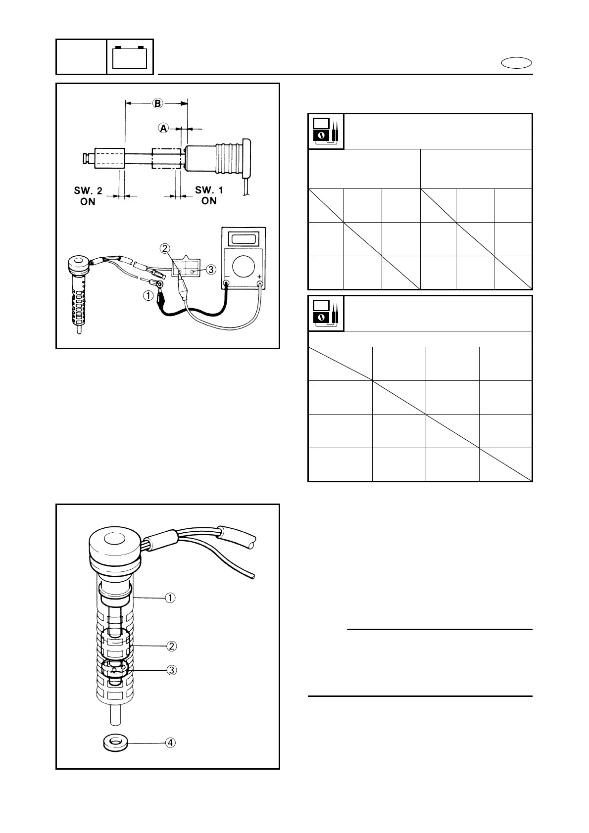
ELECTRICAL ANALYSIS
75, 80, 90 hp
Marking: 6H1-15 Unit: Ω
* “∞” indicates that the pointer deflects
once and returns to “∞”.
∞ : Discontinuity
3. Assemble as shown in the diagram.
1 Strainer cover
2 Float (Magnet)
3 Plate
4 Gasket
NOTE:
● Place the float with the magnet side
upward.
● Assemble the plate which has a hole at
the bottom.
Oil level sensor resistance
Float SW.1 ON
A 5.8 ~ 8.8 mm
(0.23 ~ 0.35 in)
Float SW. 2 ON
B 42.3 ~ 45.3 mm
(1.67 ~ 1.78 in)
1
Black
2
Green
1
Black
3
Green/
Red
1
Black
0
1
Black
*∞
2
Green
0
3
Green/
Red
640
Oil level sensor resistance
Float SW. 1, SW. 2, both OFF
2 Green 2 Green
3 Green/
Red
1 Black ∞ *∞
2 Green ∞ ∞
3 Green/Red *∞ ∞
Tester
Tester
+
-
Tester
Tester
+
-
Tester +
Tester -