5-7
E
POWR
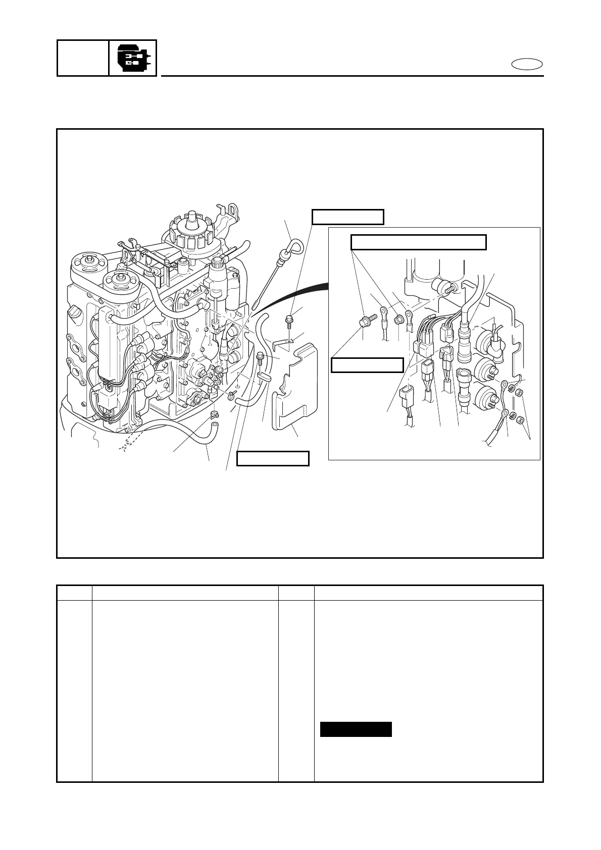
POWER UNIT
EXPLODED DIAGRAM
9 Nm (0.9 m
•
kg, 6.5 ft
•
Ib)
4
12
14
7
11
13
9
810
15
17
16
6
5
2
3
19
18
20
1
6 × 25 mm
8 × 16 mm
6 × 25 mm
REMOVAL AND INSTALLATION CHART
Step Procedure/Part name Q’ty Service points
10 PTT switch coupler 1
11 Bolt 1 On the starter motor.
12 Negative battery lead 1
13 Nut 1 On the relay (magnetic switch).
14 Positive battery lead 1
15 Nut and washer 2/2
16 PTT motor lead (blue) 1
17 PTT motor lead (green) 1
18 Plastic locking tie 2
19 Pilot water hose 1
20 Flushing water hose 1 Specifications differ.
Reverse the removal steps for installation.
Not reusable