5-36
E
POWR
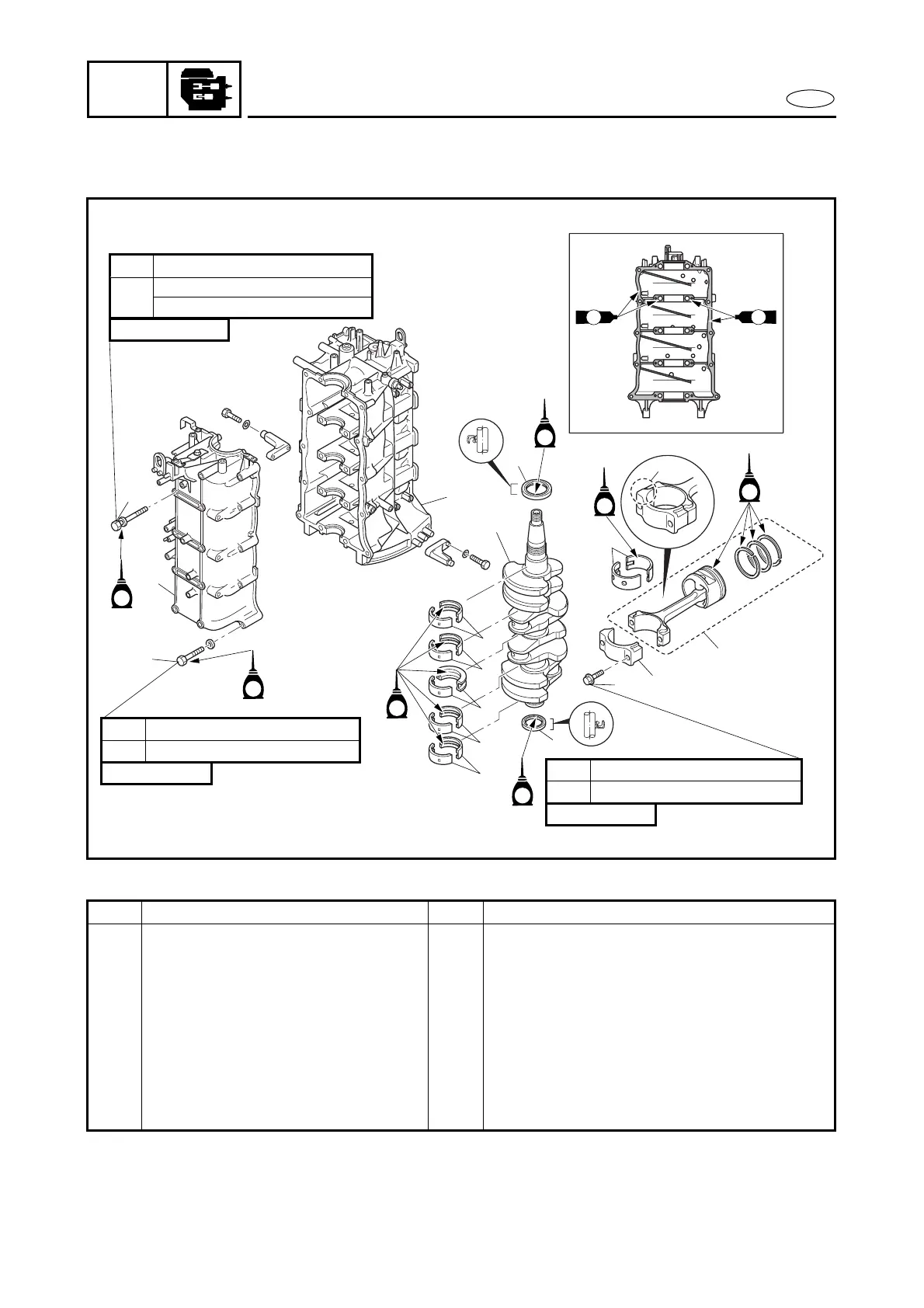
CRANKSHAFT AND PISTON/
CONNECTING ROD ASSY.
EXPLODED DIAGRAM
19 Nm (1.9 m
•
kg, 14 ft
•
Ib)1st
60°
2nd
10 × 135 mm
14 Nm (1.4 m
•
kg, 10 ft
•
Ib)1st
28 Nm (2.8 m
•
kg, 20 ft
•
Ib)2nd
8 × 55 mm
8 Nm (0.8 m
•
kg, 5.8 ft
•
Ib)1st
90°2nd
8 × 38 mm
E
E
E
E
E
E
2
3
1
7
11
9
4
8
10
12
6
5
GM
GM
GM
GM
7
7
7
7
E
a
50 Nm (5.0 m
•
kg, 36 ft
•
Ib)*
Step Procedure/Part name Q’ty Service points
6 Crankshaft 1
7 Main bearing 5 Install in the original position.
8 Big end bearing 4 Install in the original position.
9 Piston/connecting rod assy. 4 Face the large, flat side a towards the
flywheel.
10 Oil seal 1 Install the oil seals before installing the
crankcase.
11 Oil seal 1
12 Cylinder block 1
Reverse the removal steps for installation.