5-40
POWR
E
CRANKSHAFT AND PISTON/
CONNECTING ROD ASSY.
* Torque valve (for reference only)
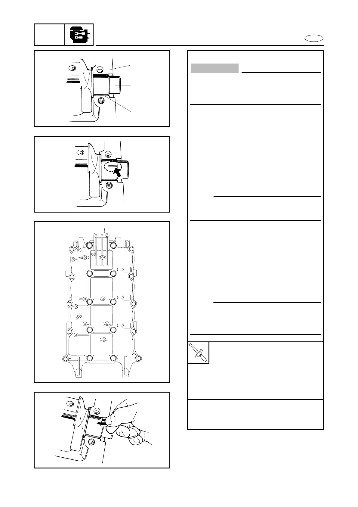
Measuring steps:
● Clean the bearings, main journals, and
bearing portions of the crankcase and
cylinder block.
● Place the cylinder block upside down
on a bench.
● Install half of the bearings 1 and the
crankshaft 2 into the cylinder block 3.
● Put a piece of Plastigauge
on each
main journal in parallel to the crank-
shaft.
● Install the other half of the bearings
into the crankcase.
● Install the crankcase onto the cylinder
block.
● Apply engine oil on to the threads and
seat of the crankcase bolts.
● Tighten the bolts to the specified
torque in two steps in the order shown
in the illustration.
T
R
.
.
Bolt (M8):
1st: 14 Nm (1.4 m • kg, 10 ft • lb)
2nd: 28 Nm (2.8 m • kg, 20 ft • lb)
Bolt (M10):
1st: 19 Nm (1.9 m • kg, 14 ft • lb)
2nd: 60˚
50 Nm (5.0 m • kg, 36 ft • lb)*
● Remove the crankcase.
● Measure the width of the compressed
Plastigauge
on each main journal.
2
3
1
I
E
A
D
H
87
G
C
B
F
J
0
9
5
K
1
4
6
2
L
33
CAUTION:
Install the bearings in their original posi-
tions. Incorrect oil clearance measure-
ments can lead to engine damage.
NOTE:
Do not put the Plastigauge
over the oil
hole in the main journal of the crankshaft.
NOTE:
Do not move the crankshaft until the
main-bearing oil clearance measurement
has been completed.