E
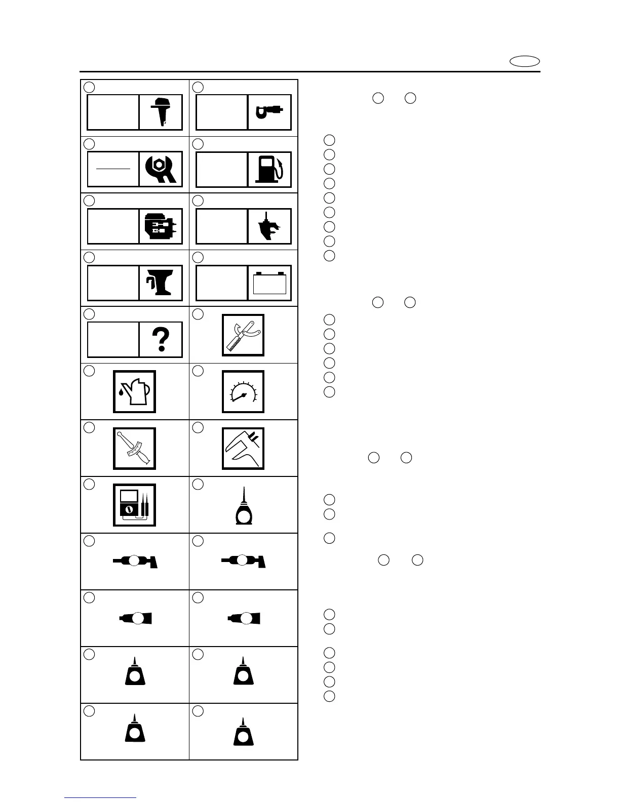
SYMBOLS
Symbols to are designed as thumb-
tabs to indicate the content of a chapter.
1
General information
2
Specifications
3
Periodic check and adjustments
4
Fuel system
5
Power unit
6
Lower unit
7
Bracket unit
8
Electrical systems
9
Trouble analysis
Symbols to indicate specific data.
10
Special tool
11
Specified liquid
12
Specified engine speed
13
Specified torque
14
Specified measurement
15
Specified electrical value
[Resistance (
Ω
), Voltage (V), Electric current
(A)]
Symbol to in an exploded diagram
indicate the grade of lubricant and the loca-
tion of the lubrication point.
16
Apply Yamaha 4-stroke motor oil
17
Apply water resistant grease
(Yamaha grease A, Yamaha marine grease)
18
Apply molybdenum disulfide oil
Symbols to in an exploded dia-
gram indicate the grade of the sealing or
locking agent and the location of the appli-
cation point.
19
Apply Gasket Maker
®
20
Apply Yamabond #4
(Yamaha bond number 4)
21
Apply LOCTITE
®
No.271 (Red LOCTITE)
22
Apply LOCTITE
®
No.242 (Blue LOCTITE)
23
Apply LOCTITE
®
No.572
24
Apply silicon sealant
1 2
3 4
5 6
7 8
9 10
11 12
13 14
15 16
17 18
19 20
21 22
23 24
GEN
INFO
SPEC
CHK
ADJ
FUEL
POWR LOWR
BRKT
–+
ELEC
TRBL
ANLS
T
R
.
.
E
A
M
GM
4
271
LT
242
LT
572
LT
LT
SS
1 9
10 15
16 18
19 24
 Loading...


