TILT CYLINDER ASSEMBLY
7-27
E
BRKT
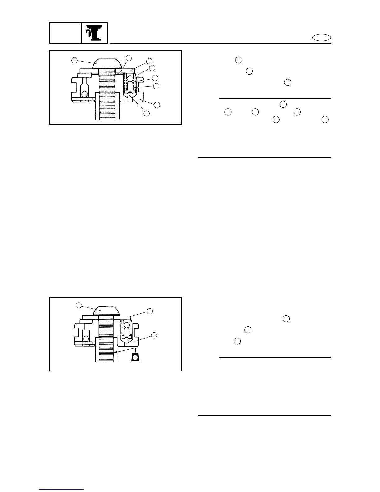
2. Remove:
•Bolt
•Washer
• Tilt piston assembly
NOTE:
Place the adjusting shims (if equipped),
springs , pins and balls between
the tilt piston assembly and washer .
If the adjusting shims, springs, pins, and
balls are not installed in their original posi-
tions the Power trim and tilt unit will not
operate properly.
CHECKING THE TILT RAM
Check:
• Tilt ram
Excessive scratches → Replace.
Bends/excessive ccorrosion →
Replace.
Rust → Polish.
(with 400 - 600 grit sandpaper)
ASSEMBLING THE TILT RAM
Install:
• Tilt piston assembly
•Washer
•Bolt
NOTE:
• Apply a thin coat of LOCTITE
®
to the tilt
ram threads. Do not let any LOCTITE
®
contact the tilt piston assembly and tilt
ram contacting surfaces.
• To open the manual valve, turn it clock-
wise.
1
a
2
d
b
c
3
d
1
2
3
a
b c d
3 2
LT
1
2
3
271
3
2
1