POWR
5-21
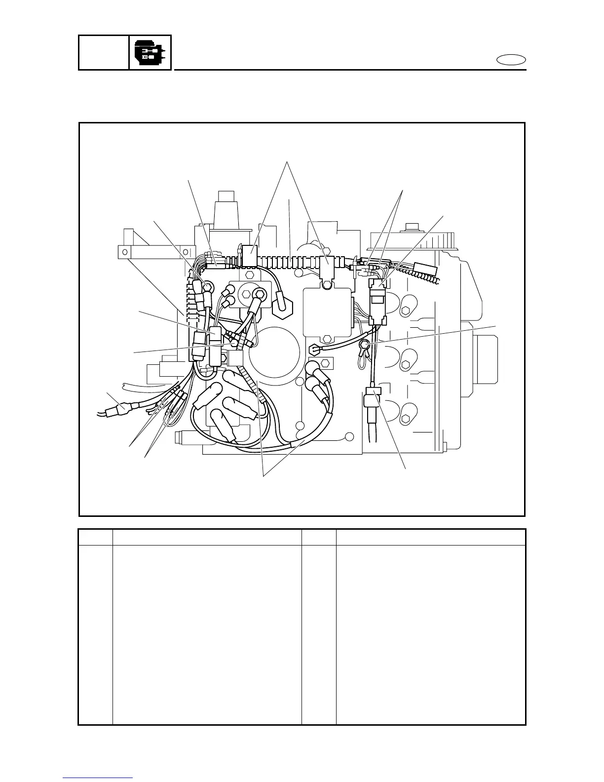
ELECTRICAL UNIT
E
REMOVING/INSTALLING THE ELECTRICAL UNIT 2
1
9
12
10
8
7
5
6
2
4
11
3
13
14
Order Job/Part Q’ty Remarks
1 Oil pressure switch connector 1 Pink
2 Ground lead 1
3 Starter relay coupler 1 (ED)
4 Ground lead 2
5 Warning light coupler 1 (MHD, WHD)
6 Neutral switch connector 2 Brown (MHD, WHD, ED-7 pin)
7 Power trim and tilt relay connector 2 Light green, Sky blue (ED)
8 Power trim and tilt lead 2 (ED)
9 Thermo sensor coupler 1
10 Power trim and tilt switch coupler 2 (ED)
11 Ground lead 2
12 Rectifier/regulator connector 2 Red, Gray (WHD, ED, ET)
13 Clamp 2
Continued on next page.



 To Next Page