–+
ELEC
8-9
ELECTRICAL COMPONENTS ANALYSIS
E
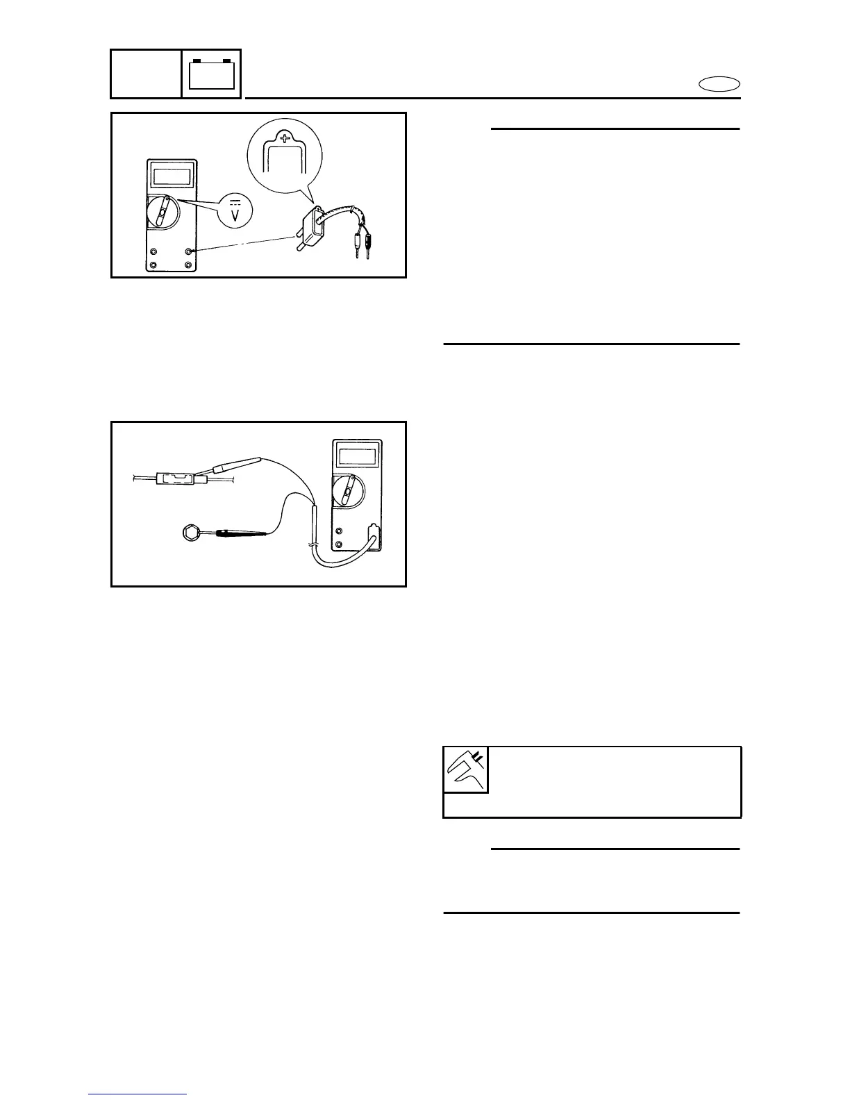
NOTE:
• When measuring the peak voltage, set
the selector to the DC voltage mode.
• Make sure the peak voltage adaptor
leads are properly installed in the digi-
tal tester.
• Make sure the positive pin (the "+"
mark facing up as shown) on the peak
voltage adaptor is installed into the
positive terminal of the digital tester.
• The test harness is needed for the fol-
lowing tests.
Measuring steps
(1) Connect the peak voltage adaptor pro-
bes to the connectors.
(2) Start or crank the engine and observe
the measurement.
MEASURING A LOW RESISTANCE
When measuring a resistance of 10 Ω or
less with the digital tester, the correct mea-
surement cannot be obtained because of
the tester’s internal resistance.
To obtain the correct value, subtract the
internal resistance from the displayed mea-
surement.
NOTE:
The internal resistance of the digital tester
can be obtained by connecting both of its
probes.
Correct value
Displayed measurement -
internal resistance