TILLER HANDLE ASSEMBLY
7-3
E
BRKT
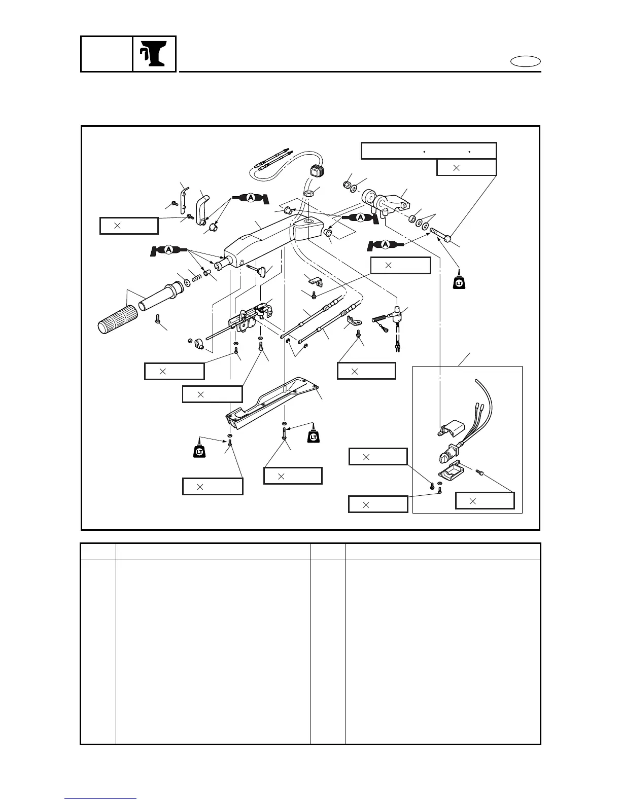
DISASSEMBLING/ASSEMBLING THE TILLER HANDLE ASSEMBLY
1
2
3
4
5
6
7
8
9
6 16 mm
6 40 mm
10
11
12
13
14
15
16
17
18
19
20
21
22
23
24
25
26
27
28
29
30
31
32
33
34
35
34
572
572
6 26 mm
8 40 mm
37 Nm(3.7 m kgf, 27 ft lb)
12 80 mm
6 14 mm
6 14 mm
6 30 mm
6 14 mm
572
6 24 mm
6 20 mm
Order Job/Part Q’ty Remarks
1 Screw 5
2 Screw 2
3 Cover 1
4Nut 1
5 Engine stop switch 1
6 Main switch assembly 1 (WHD)
7Bolt 1
8 Clamp 1 For shift cable
9Bolt 1
10 Clamp 1 For throttle cable
11 Circlip 2
12 Shift cable 1 Long
13 Throttle cable 1 Short
Continued on next page.
 Loading...


