8. Install:
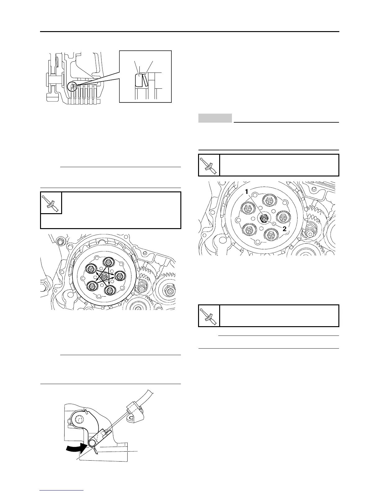
Tighten the clutch spring bolts in two stages and
in a crisscross pattern.
9. Check:
● Push lever position
Push lever mark “a” and crankcase mark “b”
not aligned → Correct.
NOTE:
Move the push lever in the arrow direction with
your fingers, and check that it feels heavier
when its mark aligns.
10.Adjust:
●
Push lever position
▼▼▼▼▼▼▼▼▼▼▼▼▼▼▼▼▼▼▼▼▼▼▼▼▼▼▼▼▼▼▼▼
a. Loosen the locknut “1”.
b. Turn the adjusting screw “2” in or out until the
marks are aligned.
c. Hold the adjusting screw to prevent it from
moving and then tighten the locknut to speci-
fication.
CAUTION:
ECA13820
Do not overtighten the locknut since this will
remove the free play between both push
rods.
▲▲▲▲▲▲▲▲▲▲▲▲▲▲▲▲▲▲▲▲▲▲▲▲▲▲▲▲▲▲▲▲
11.Install:
●
Clutch cover “1”
NOTE:
Tighten the bolts diagonally.
● M6 × 25 mm bolt “2”
● M6 × 35 mm bolt “3”
●
M6 × 50 mm bolt “4”
● M6 × 50 mm bolt (with gasket)“5”
● M6 × 55 mm bolt (with gasket)“6”
Adjusting screw lock nut
8 Nm (0.8 m•kg, 5.8 ft•lb)
Clutch spring bolt
8 Nm (0.8 m•kg, 5.8 ft•lb)
1 2
T
R
.
.
b
a
Locknut
8 Nm (0.8 m•kg, 5.8 ft•lb)
Clutch cover bolt
10 Nm (1.0 m•kg, 7.2 ft•lb)
T
R
.
.
T
R
.
.



 To Next Page