EAS20090
HOW TO USE THIS MANUAL
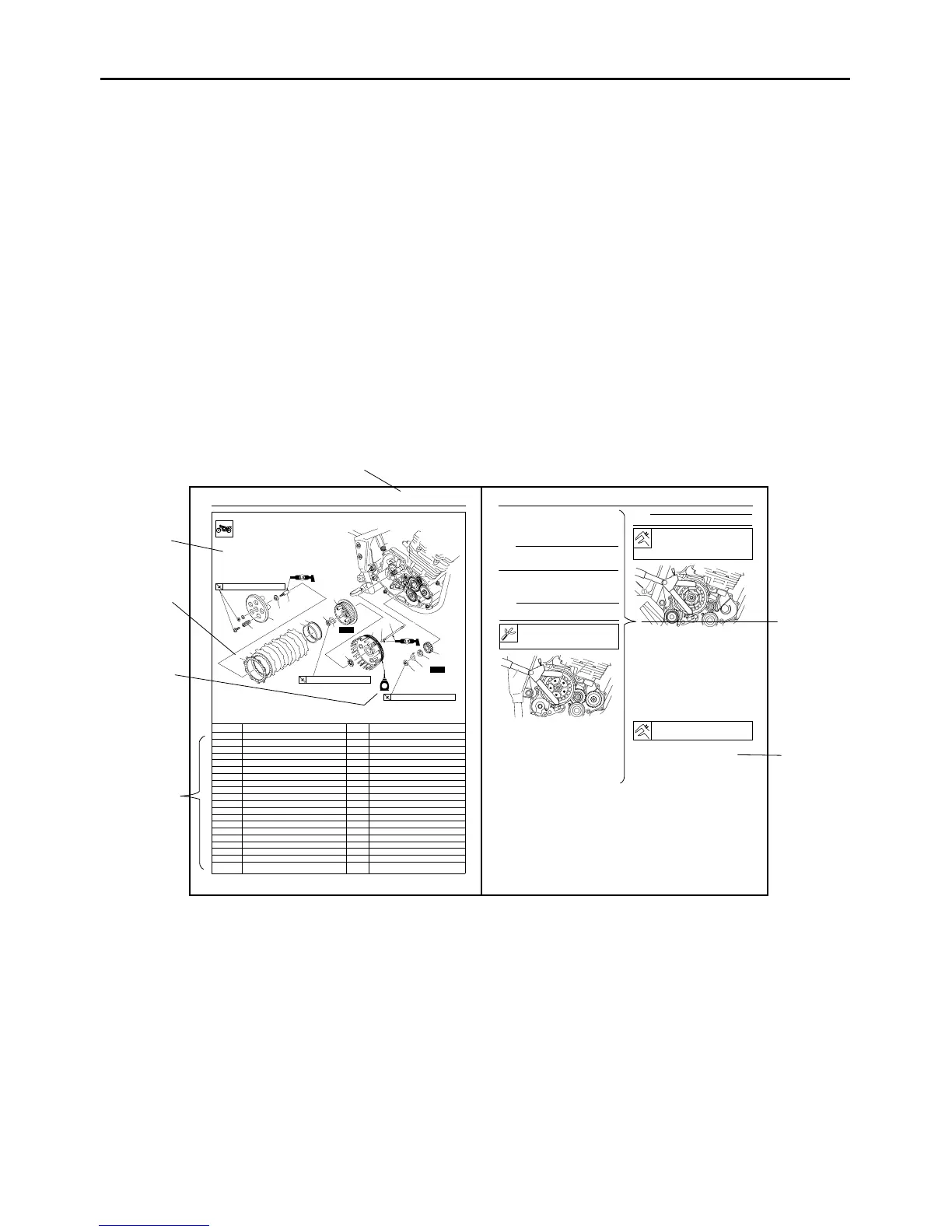
This manual is intended as a handy, easy-to-read reference book for the mechanic. Comprehensive
explanations of all installation, removal, disassembly, assembly, repair and check procedures are laid
out with the individual steps in sequential order.
● The manual is divided into chapters and each chapter is divided into sections. The current section title
is shown at the top of each page “1”.
●
Sub-section titles appear in smaller print than the section title “2”.
● To help identify parts and clarify procedure steps, there are exploded diagrams at the start of each
removal and disassembly section “3”.
● Numbers are given in the order of the jobs in the exploded diagram. A number indicates a disassem-
bly step “4”.
● Symbols indicate parts to be lubricated or replaced “5”.
Refer to “SYMBOLS”.
● A job instruction chart accompanies the exploded diagram, providing the order of jobs, names of
parts, notes in jobs, etc “6”.
● Jobs requiring more information (such as special tools and technical data) are described sequentially
“7”.
7
2
CLUTCH
5-31
Removing the clutch
Order Job/Parts to remove Q’ty Remarks
1 Clutch spring 5
2 Pressure plate 1
3 Adjusting screw 1
4 Push plate 1
5 Friction plate 6
6 Clutch plate 5
7 Clutch damper spring 1
8 Clutch damper spring seat 1
9 Primary drive gear nut 1
10 Lock washer 1
11 Claw washer 1
12 Clutch boss nut 1
13 Lock washer 1
14 Clutch boss 1
15 Thrust washer 1
16 Clutch housing 1
17 Ball 1
18 Clutch push rod 1
19 Primary drive gear 1
For installation, reverse the removal proce-
dure.
New
New
E
T
R
.
.
8 Nm (0.8 m • kg, 5.8 ft • Ib)
T
R
.
.
75 Nm (7.5 m • kg, 54 ft • Ib)
T
R
.
.
80 Nm (8.0 m • kg, 58 ft • Ib)
1
2
5
6
7
8
12
13
15
16
17
9
10
11
19
18
14
3
4
(5)
3
4
5
6
1
CLUTCH
5-33
EAS25070
REMOVING THE CLUTCH
1. Straighten the lock washer tab.
2. Loosen:
Primary drive gear nut “1”
NOTE:
Insert aluminum plate “a” between primary drive
gear “2” and primary driven gear “3”, and loosen
the primary drive gear nut.
3. Loosen:
Clutch boss nut “1”
NOTE:
While holding the clutch boss “1” with the univer-
sal clutch holder “2”, loosen the clutch boss nut.
EAS25100
CHECKING THE FRICTION PLATES
The following procedure applies to all of the fric-
tion plates.
1. Check:
Friction plate
Damage/wear Replace the friction plates
as a set.
2. Measure:
Friction plate thickness
Out of specification Replace the friction
plates as a set.
NOTE:
Measure the friction plate at four places.
EAS25110
CHECKING THE CLUTCH PLATES
The following procedure applies to all of the
clutch plates.
1. Check:
Clutch plate
Damage Replace the clutch plates as a
set.
2. Measure:
Clutch plate warpage
(with a surface plate and thickness gauge “1”)
Out of specification Replace the clutch
plates as a set.
EAS25140
CHECKING THE CLUTCH SPRINGS
The following procedure applies to all of the
clutch springs.
1. Check:
Clutch spring
Damage Replace the clutch springs as a
set.
2. Measure:
Universal clutch holder
90890-04086
YM-91042
2
1
3
Friction plate thickness
2.70—2.90 mm (0.106—0.114 in)
Wear limit
2.60 mm (0.1024 in)
Warpage limit
0.20 mm (0.0079 in)