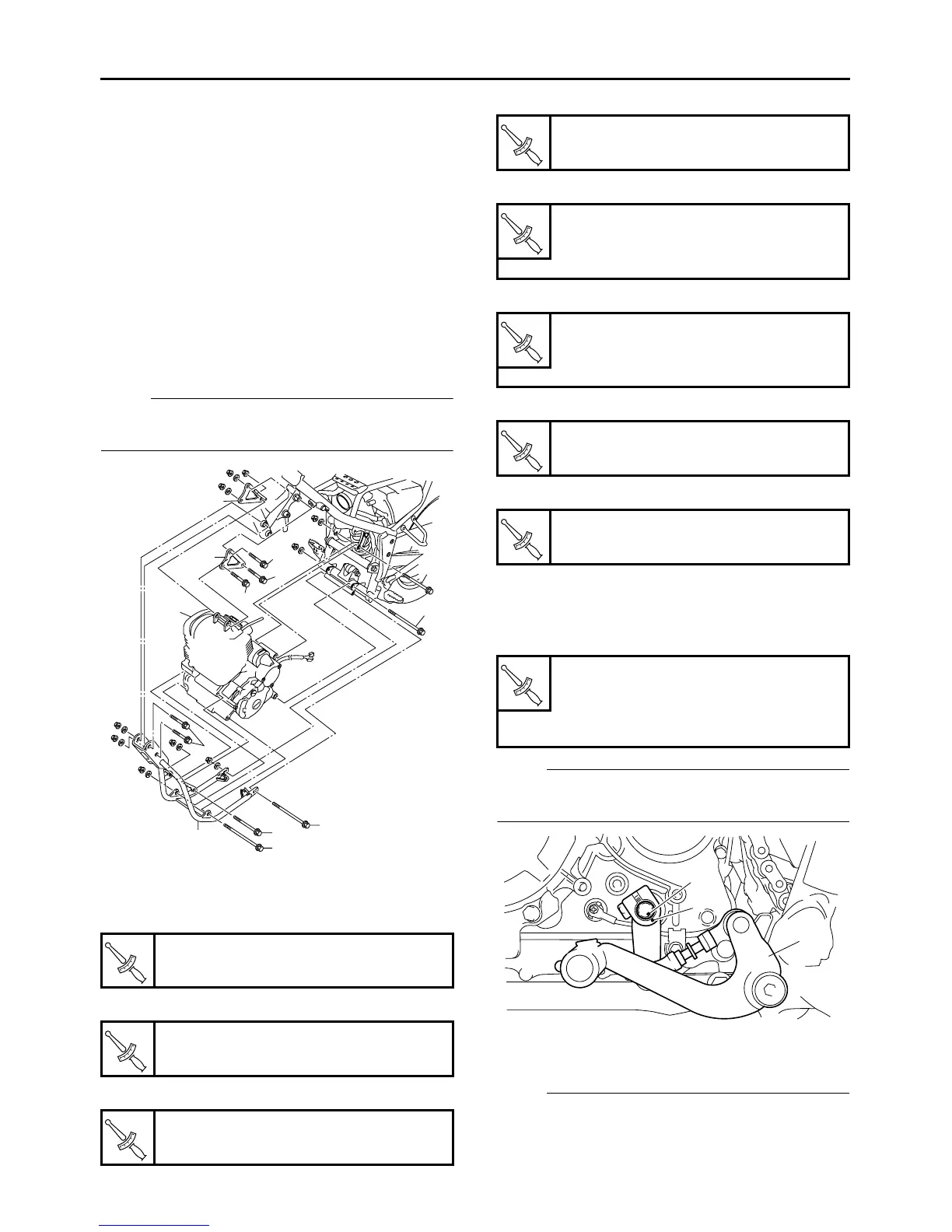
1. Install:
The bolts and nuts must be tightened temporari-
ly in this stage.(Temporarily tighten)
2. Tighten:
● Engine mounting nut (rear upper)
●
Engine mounting nut (rear lower)
● Down tube nut (rear)
● Down tube nut (front)
●
Engine mounting nut (front upper)
● Engine mounting nut (front upper)
● Engine bracket nut
● Engine mounting nut (upper)
EAS3C51004
INSTALLING THE SHIFT PEDAL
1. Install:
● Shift pedal assembly “1”
NOTE:
Align mark “a” of the shift shaft with mark “b” of
the shift arm.
2. Adjust:
● Shift pedal position
NOTE:
Loosen the lock nut “1” and turn shift rod “2” so
that height “a” from the footrest to the shift pedal
top face comes within 16 to 22 mm (0.63 to 0.79
Engine mounting nut (rear upper)
60 Nm (6.0 m•kg, 43 ft•lb)
Engine mounting nut (rear lower)
60 Nm (6.0 m•kg, 43 ft•lb)
Down tube nut (rear)
60 Nm (6.0 m•kg, 43 ft•lb)
3
12
11
11
9
10
1
6
4
8
7
5
2
T
R
.
.
T
R
.
.
T
R
.
.
Down tube nut (front)
60 Nm (6.0 m•kg, 43 ft•lb)
Engine mounting nut (front up-
per)
60 Nm (6.0 m•kg, 43 ft•lb)
Engine mounting nut (front up-
per)
60 Nm (6.0 m•kg, 43 ft•lb)
Engine bracket nut
44 Nm (4.0 m•kg, 32 ft•lb)
Engine mounting nut (upper)
60 Nm (6.0 m•kg, 43 ft•lb)
Shift pedal bolt
30 Nm (3.0 m•kg, 22 ft•lb)
Shift arm bolt
10 Nm (1.0 m•kg, 7.2 ft•lb)
T
R
.
.
T
R
.
.
T
R
.
.
T
R
.
.
T
R
.
.
T
R
.
.
a
b
1
 Loading...