ELECTRICAL COMPONENTS
7-46
▲▲▲▲▲▲▲▲▲▲▲▲▲▲▲▲▲▲▲▲▲▲▲▲▲▲▲▲▲▲▲▲
EAS28240
CHECKING THE SPEED SENSOR
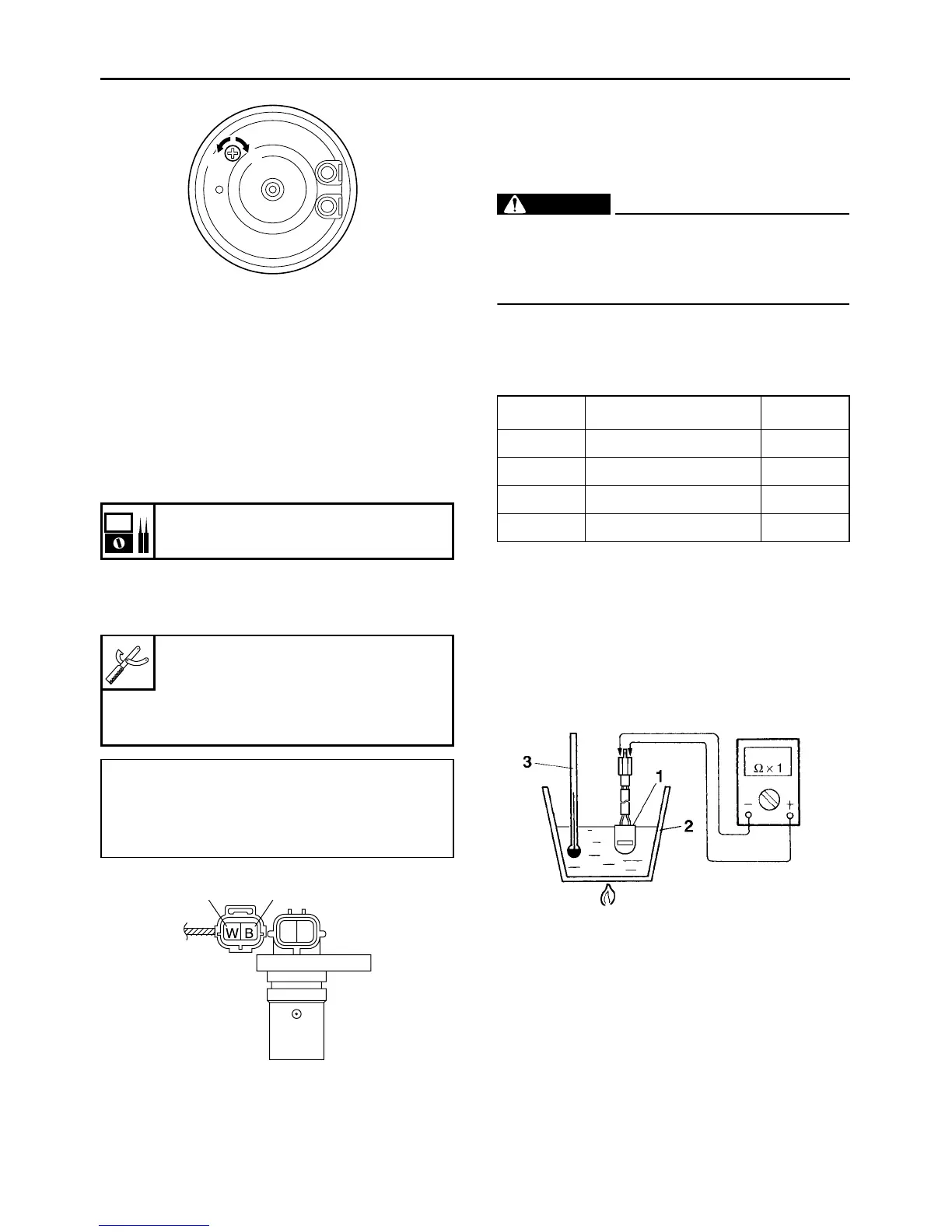
1. Disconnect:
● Speed sensor coupler
2. Check:
● Speed sensor resistance
Out of specification → Replace.
▼▼▼▼▼▼▼▼▼▼▼▼▼▼▼▼▼▼▼▼▼▼▼▼▼▼▼▼▼▼▼▼
a. Connect the digital circuit tester to the speed
sensor coupler (wire harness side).
b. Measure the speed sensor resistance.
▲▲▲▲▲▲▲▲▲▲▲▲▲▲▲▲▲▲▲▲▲▲▲▲▲▲▲▲▲▲▲▲
EAS28270
CHECKING THE THERMO SWITCH
1. Remove:
● Thermo switch
(from the thermostat housing)
WARNING
EWA13830
● Handle the thermo switch with special care.
● Never subject the thermo switch to strong
shocks. If the thermo switch is dropped, re-
place it.
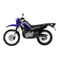
2. Check:
● Thermo switch continuity
Out of specification → Replace the thermo
switch.
Step 1 and 2: Heating phase
Step 3 and 4: Cooling phase
▼▼▼▼▼▼▼▼▼▼▼▼▼▼▼▼▼▼▼▼▼▼▼▼▼▼▼▼▼▼▼▼
a. Connect the pocket tester (Ω × 1) to the ther-
mo switch “1” as shown.
b. Immerse the thermo switch in a container
filled with coolant “2”.
c. Place a thermometer “3” in the coolant.
d. Slowly heat the coolant, then let it cool down
to the specified temperature.
Speed sensor resistance
470–530 Ω 25 °C (77 °F)
Digital circuit tester
90890-03174
Model 88 Multimeter with tachom-
eter
YU-A1927
Positive tester probe
White “1”
Negative tester probe
Black “2”
a
b
21
Test step Coolant temperature
Continuity
1 Less than 16°C (61°F) YES
2 More than 16°C (61°F) NO
3 More than 11°C (52°F) NO
4 Less than 11°C (52°F) YES