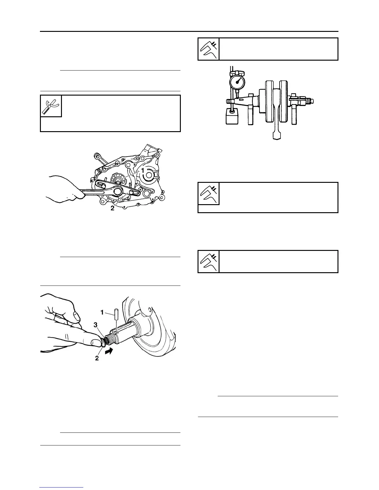
1. Remove:
Remove the crankshaft assembly using crank-
shaft separating tool “2”.
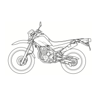
2. Remove:
●
Dowel pin “1”
● Plunger pin “2”
● Spring “3”
NOTE:
Slightly press the plunger pin and pull out the
dowel pin. Then, remove the plunger pin and the
spring.
EAS3C51014
CHECKING THE CRANKSHAFT AND
CONNECTING ROD
1. Measure:
●
Crankshaft runout
Out of specification → Replace the crank-
shaft assembly, bearing or both.
NOTE:
Turn the crankshaft slowly.
2. Measure:
●
Big end side clearance
Out of specification → Replace the crank-
shaft assembly.
3. Measure:
●
Crankshaft width
Out of specification → Replace the crank-
shaft assembly.
4. Check:
● Bearing
Cracks/damage/wear → Replace the crank-
shaft assembly.
5. Check:
● Crankshaft journal oil passage
Obstruction → Blow out with compressed air.
EAS26210
INSTALLING THE CRANKSHAFT
ASSEMBLY
1. Install:
● Spring “1”
● Plunger pin “2”
● Dowel pin “3”
NOTE:
Press the plunger pin by your fingers, and make
sure that it operates smoothly.
Crankcase separating tool
90890-01135
Crankcase separator
YU-01135-B
Runout limit C
0.030 mm (0.0012 in)
Big end side clearance D
0.350–0.850 mm (0.0138–0.0335
in)
Width A
69.25–69.30 mm (2.726–2.728 in)