● Valve clearance adjustment should be made
on a cold engine, at room temperature.
● When the valve clearance is to be measured or
adjusted, the piston must be at top dead center
(TDC) on the compression stroke.
1. Remove:
● Fuel tank
Refer to “FUEL TANK” on page 6-1.
2. Remove:
● Intake tappet cover “1”
●
Exhaust tappet cover “2”
● Camshaft sprocket cover “3”
3. Remove:
● Spark plug cap
● Spark plug
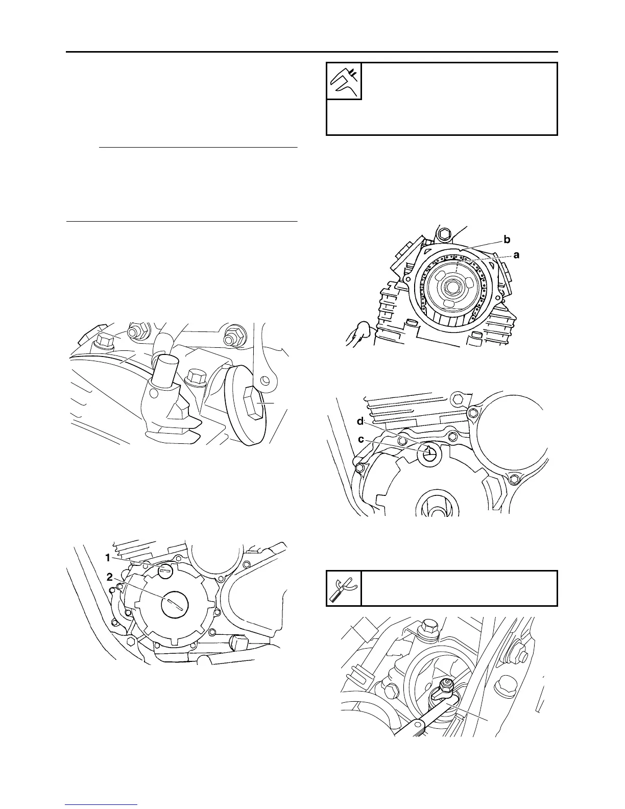
4. Remove:
● Timing mark accessing screw “1”
● Crankshaft end cover “2”
5. Measure:
● Valve clearance
Out of specification → Adjust.
▼▼▼▼▼▼▼▼▼▼▼▼▼▼▼▼▼▼▼▼▼▼▼▼▼▼▼▼▼▼▼▼
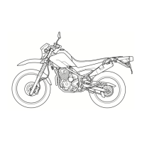
a. Turn the crankshaft counterclockwise.
b. When the piston is in the compression stroke,
align camshaft sprocket mark “a” with cylin-
der head mark “b”. This is the Top Dead Cen-
ter (TDC).
c. Make sure that generator rotor mark “c”
aligns with generator rotor cover mark “d”.
d. Measure the valve clearance using special
thickness gauge “1”.
Out of specification → Adjust.
1
3
2
Valve clearance (cold)
Intake
0.05–0.10 mm (0.0020–0.0039 in)
Exhaust
0.10–0.15 mm (0.0039–0.0059 in)
Special thickness gauge
90890-01399
1