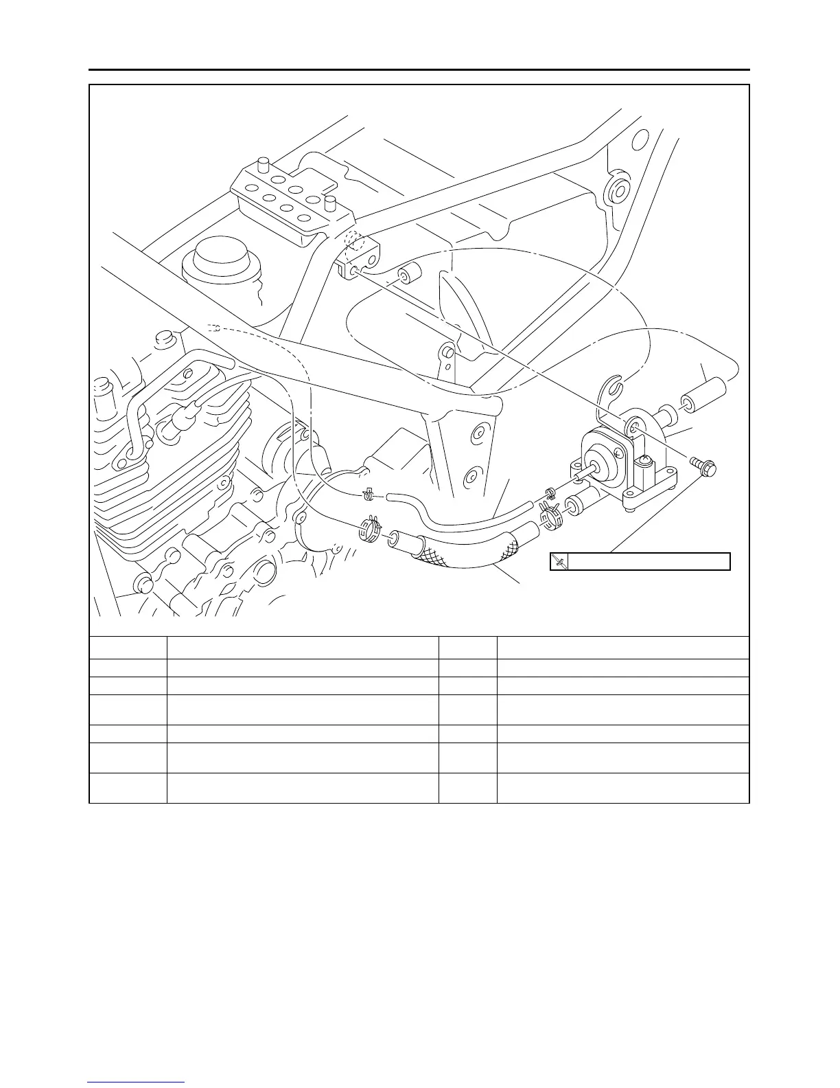
AIR INDUCTION SYSTEM
6-11
Removing the air cut-off valve and hose
Order Job/Part Q’ty Remarks
Fuel tank Refer to “FUEL TANK” on page 6-1.
1 Air induction system vacuum hose 1
2
Air induction system hose (from the air cut-off
valve to the cylinder head)
1
3 Air cut-off valve 1
4
Air induction system hose (from the air filter to
the air cut-off valve)
1
For installation, reverse the removal proce-
dure.
T
R
.
.
7 Nm (0.7 m • kg, 5.1 ft • Ib)
1
2
3
4



 To Next Page