B95W
Description
05_Beschreibung_en.fm - V1.0 - 1.8.17
65 / 306
5
11
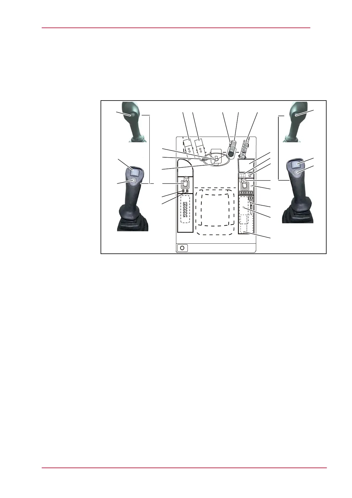
5.3 Display and control elements in the operator's
compartment
5.3.1 Controls
Fig. 5-11 Control elements
1 Apportionable driving
2 Actuation - intermediate boom/articulation
3 Excavator brake unlocking
4 Service brake/excavator brake
5 Accelerator pedal
6 Display
7 Keypad
8 Start switch
9 Joystick - excavator equipment right
9-1 Continuous operation for additional control circuits
9-2 Actuate dial for additional control circuit 1
9-3 Articulated boom changeover
10 Move forward/backward
11 Engine speed setting (manual throttle)
12 Power socket 12 V
13 Optional - radio
14 Right-hand support
15 Left-hand support
16 Joystick, left
16-1 Signal horn
16-2 Actuate dial for auxiliary control circuit 2
16-3 Slewing pressure switch
17 Steering wheel angle adjustment pedal
18 Signal horn, direction indicator and light switch
19 Button for steering wheel height adjustment
19
12 3 4
5
7
8
9
10
11
15
12
14
13
16
18
17
9-1
9-2
9-3
6
16-1
16-2
16-3