5-18
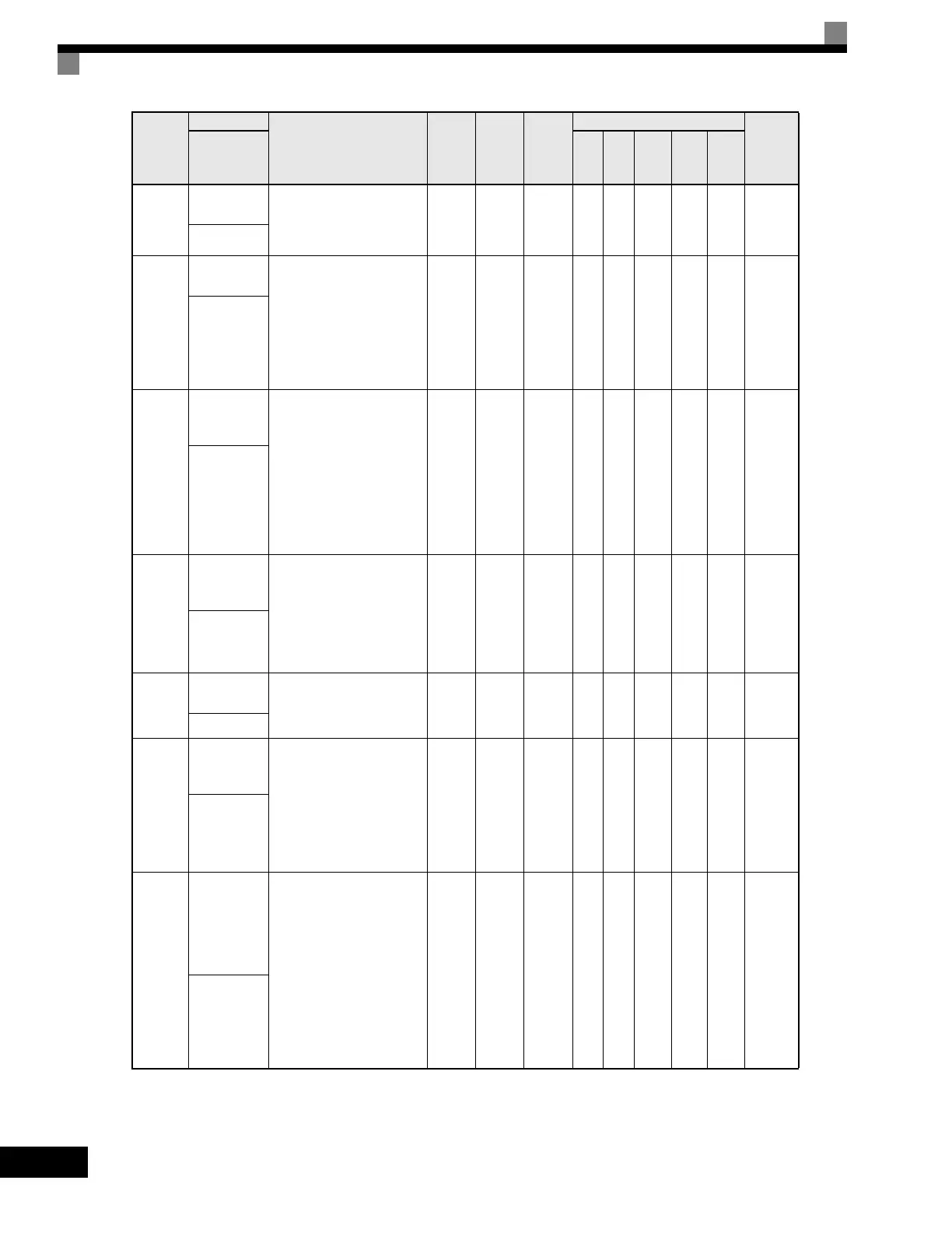
b5-06
PID Output
Limit
Sets the maximum output
possible from the entire PID
controller. Set as a percentage
(%) of maximum frequency.
0.0
to
100.0
100.0% Yes A A A A A 1AAH
PID Limit
b5-07
PID Offset
Adjustment
Sets the amount of offset of the
output of the PID controller.
Set as a percentage (%) of
maximum frequency.
The offset is summed with the
PID output. This can be used
to artificially kick-start a slow
starting PID loop.
-100.0
to
100.0
0.0% Yes A A A A A 1ABH
PID Offset
b5-08
PID Primary
Delay Time
Constant
Sets the amount of time for
the filter on the output of the
PID controller.
Note: The offset is summed
with the PID output.
This can be used to
artifically kick-start a
slow starting PID loop.
Note: Normally, change is not
required.
0.00
to
10.00
0.00 s Yes A A A A A 1ACH
PID Delay
Time
b5-09
PID Output
Level
Selection
Determines whether the PID
controller will be direct or
reverse acting.
0: Normal Output (direct
acting)
1: Reverse Output (reverse
acting)
0 or 1 0 No A A A A A 1ADH
Output Level
Sel
b5-10
PID Output
Gain Setting
Sets the output gain of the
PID controller.
0.0
to
25.0
1.0 No A A A A A 1AEH
Output Gain
b5-11
PID Output
Reverse
Selection
0: Zero Limit (when PID
output goes negative,
Drive stops). Zero Limit is
automatic when reverse
prohibit is selected using
b1-04.
1: Reverse (when PID goes
negative, Drive reverses).
0 or 1 0 No A A A A A 1AFH
Output Rev
Sel
b5-12
PID
Feedback
Reference
Missing
Detection
Selection
0: Disabled (no detection of
loss of PID feedback)
1: Alarm (detection of loss
of PID feedback,
operation continues
during detection with the
fault contact not
energized)
2: Fault (detection of loss of
PID feeedback, coast to
stop during detection and
fault contact energizes)
0 to 2 0 No A A A A A 1B0H
Fb los Det Sel
Parameter
Number
Name
Description
Setting
Range
Factory
Setting
Change
during
Operation
Control Methods
MODBUS
Register
Display
V/f
V/f
with
PG
Open
Loop
Vector
1
Flux
Vector
Open
Loop
Vector
2
Artisan Technology Group - Quality Instrumentation ... Guaranteed | (888) 88-SOURCE | www.artisantg.com

 Loading...


