5-48
Communications Option Cards: F6
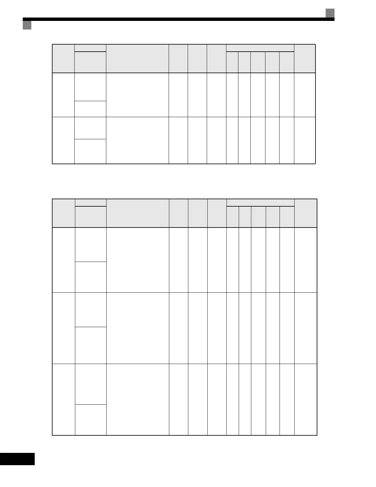
User parameters for a Communications Option Card are shown in the following table.
F5-08
DO-08
Channel 8
Output
Selection
Sets the digital output
function number for channel 8.
See the H2 parameter group
for possible selections.
Enabled when digital output
card DO-02 or DO-08 is used.
0 to 37 0F No A A A A A 3A0H
DO Ch8
Select
F5-09
DO-08
Output Mode
Selection
Sets the function of the DO-08
digital output option board.
0: 8-channel individual outputs.
1: Binary code output.
2: 8-channel Selected -
Output according to F5-01
to F5-08 settings.
0 to 2 0 No A A A A A 3A1H
DO-08
Selection
Parameter
Number
Name
Description
Setting
Range
Factory
Setting
Change
during
Operation
Control Methods
MODBUS
Register
Display
V/f
V/f
with
PG
Open
Loop
Vector
1
Flux
Vector
Open
Loop
Vector
2
F6-01
Operation
Selection
after
Communication
Error
Selects the stopping method
for a communication option
board fault (BUS). Active
only when a communication
option board is installed and
b1-01 or b1-02 = 3.
0: Ramp to Stop
1: Coast to Stop
2: Fast-Stop
3: Alarm Only
0 to 3 1 NoAAAAA3A2H
Comm BUS
Flt Sel
F6-02
Selection of
External
Fault from
Communication
Option Board
Selects the condition in
which an EF0 fault is
detected from a
communication option
board. Active only when a
communication option board
is installed and b1-01 or
b1-02 = 3.
0: Always detected.
1: Detected only during
operation.
0 or 1 0 NoAAAAA3A3H
EF0
Detection
F6-03
Stopping
Method for
External
Fault from
Communication
Option Board
Selects the stopping method
for an external fault from a
communication option board
(EF0). Active only when a
communication option board
is installed and b1-01 or
b1-02 = 3.
0: Ramp to Stop
1: Coast to Stop
2: Fast-Stop
3: Alarm Only
0 to 3 1 NoAAAAA3A4H
EF0 Fault
Action
Parameter
Number
Name
Description
Setting
Range
Factory
Setting
Change
during
Operation
Control Methods
MODBUS
Register
Display
V/f
V/f
with
PG
Open
Loop
Vector
1
Flux
Vector
Open
Loop
Vector
2
Artisan Technology Group - Quality Instrumentation ... Guaranteed | (888) 88-SOURCE | www.artisantg.com

 Loading...


