6-92
Note Write 0 to all unused bits. Also, do not write data to reserved registers.
Monitor Data
The following table shows the monitor data. Monitor data can only be read.
000FH
Reference selection settings
Bit 0 Not used
Bit 1 Use MODBUS 0006H PID target value
Bits 2 to B Not used
C Broadcast data terminal S5 input 1: Enabled 0: Disabled
D Broadcast data terminal S6 input 1: Enabled 0: Disabled
E Broadcast data terminal S7 input 1: Enabled 0: Disabled
F Broadcast data terminal S8 input 1: Enabled 0: Disabled
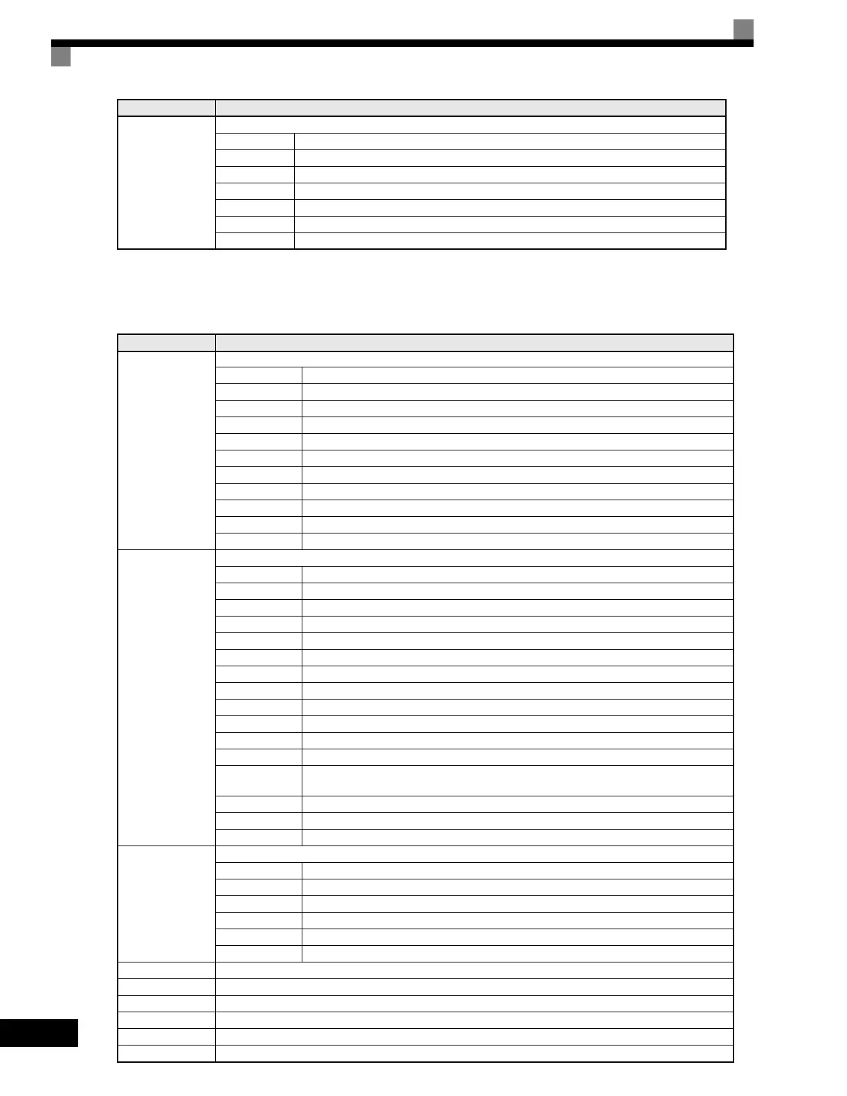
Register No. Contents
0020H
Drive status
Bit 0 Operation 1: Operating 0: Stopped
Bit 1 Reverse operation 1: Reverse operation 0: Forward operation
Bit 2 Drive startup complete 1: Completed 2: Not completed
Bit 3 Error 1: Error
Bit 4 Data setting error 1: Error
Bit 5 Multi-function contact output 1 (terminal M1 - M2) 1: ON 0: OFF
Bit 6 Multi-function contact output 2 (terminal M3 - M4) 1: ON 0: OFF
Bit 7 Multi-function contact output 3 (terminal M5 - M6) 1: ON 0: OFF
Bit 8 Multi-function PHC output 3 (terminal P3 - C3) 1: ON 0: OFF
Bit 9 Multi-function PHC output 4 (terminal P4 - C4) 1: ON 0: OFF
Bits A and B Not used
0021H
Error details
Bit 0 Overcurrent (OC) Ground fault (GF)
Bit 1 Main circuit overvoltage (OV)
Bit 2 Drive overload (OL2)
Bit 3 Drive overheat (OH1, OH2)
Bit 4 Injection brake transistor resistance overheat (rr, rH)
Bit 5 Fuse blown (PUF)
Bit 6 PID feedback reference lost (FbL)
Bit 7 External fault (EF, EFO)
Bit 8 Hardware error (CPF)
Bit 9 Motor overload (OL1), overtorque 1 (OL3) detected, or overtorque 2 (OL4) detected
Bit A PG broken wire detected (PGO), Overspeed (OS), Speed deviation (DEV)
Bit B Main circuit undervoltage (UV) detected
Bit C
Main circuit undervoltage (UV1), control power supply error (UV2), inrush preven-
tion circuit error (UV3), power loss
Bit D SPO output phase open, SPI output phase open
Bit E MODBUS communications error (CE)
Bit F Operator disconnected (OPR)
0022H
Data link status
Bit 0 Writing data
Bit 1 Not used
Bit 2 Not used
Bit 3 Upper and lower limit errors
Bit 4 Data integrity error
Bits 5 to F Not used
0023H Frequency reference (U1-01)
0024H Output frequency (U1-02)
0025H Output voltage reference (U1-06)
0026H Output current (U1-03)
0027H Output power (U1-08)
0028H Torque reference (U1-09)
Register No. Contents
Artisan Technology Group - Quality Instrumentation ... Guaranteed | (888) 88-SOURCE | www.artisantg.com

 Loading...


