6-138
Time Chart
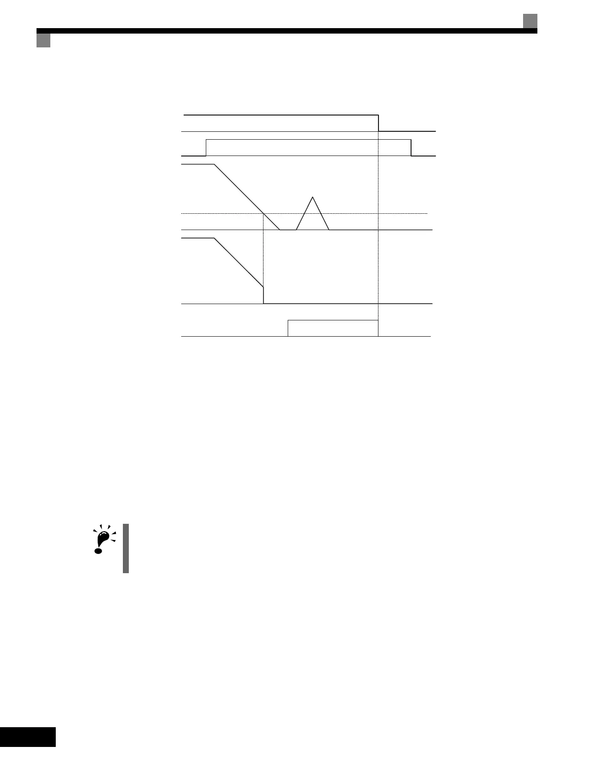
A time chart for the zero servo function is given in Fig 6.74 Time Chart for Zero Servo.
Fig 6.74 Time Chart for Zero Servo
Application Precautions
• Be sure to leave the run command input ON. If the run command is turned OFF, the output will be inter-
rupted and the zero-servo function will become ineffective.
• The holding force of the zero-servo is adjusted in b9-01. The holding force will increase if the value of the
setting is increased, but oscillation and hunting will occur if the setting is too large. Adjust b9-01 after
adjusting the speed control gain.
• The zero-servo detection width is set as the allowable position offset from the zero-servo start position. Set
4 times the number of pulses from the PG.
• The Zero Servo End signal will go OFF when the zero servo command is turned OFF.
Do not lock the servo for extended periods of time at 100% when using the zero servo function. Drive errors
may result. Extended periods of servo lock can be achieved by ensuring that the current during the servolock
is 50% or less or by increasing the Drive capacity.
Run command
ON OFF
Zero servo command
Frequency (speed) reference
Excitation level
b2-01
Motor speed
Zero Servo End signal Zero-servo status
ON OFF
Artisan Technology Group - Quality Instrumentation ... Guaranteed | (888) 88-SOURCE | www.artisantg.com

 Loading...


