2-38
Wiring the PG-B2
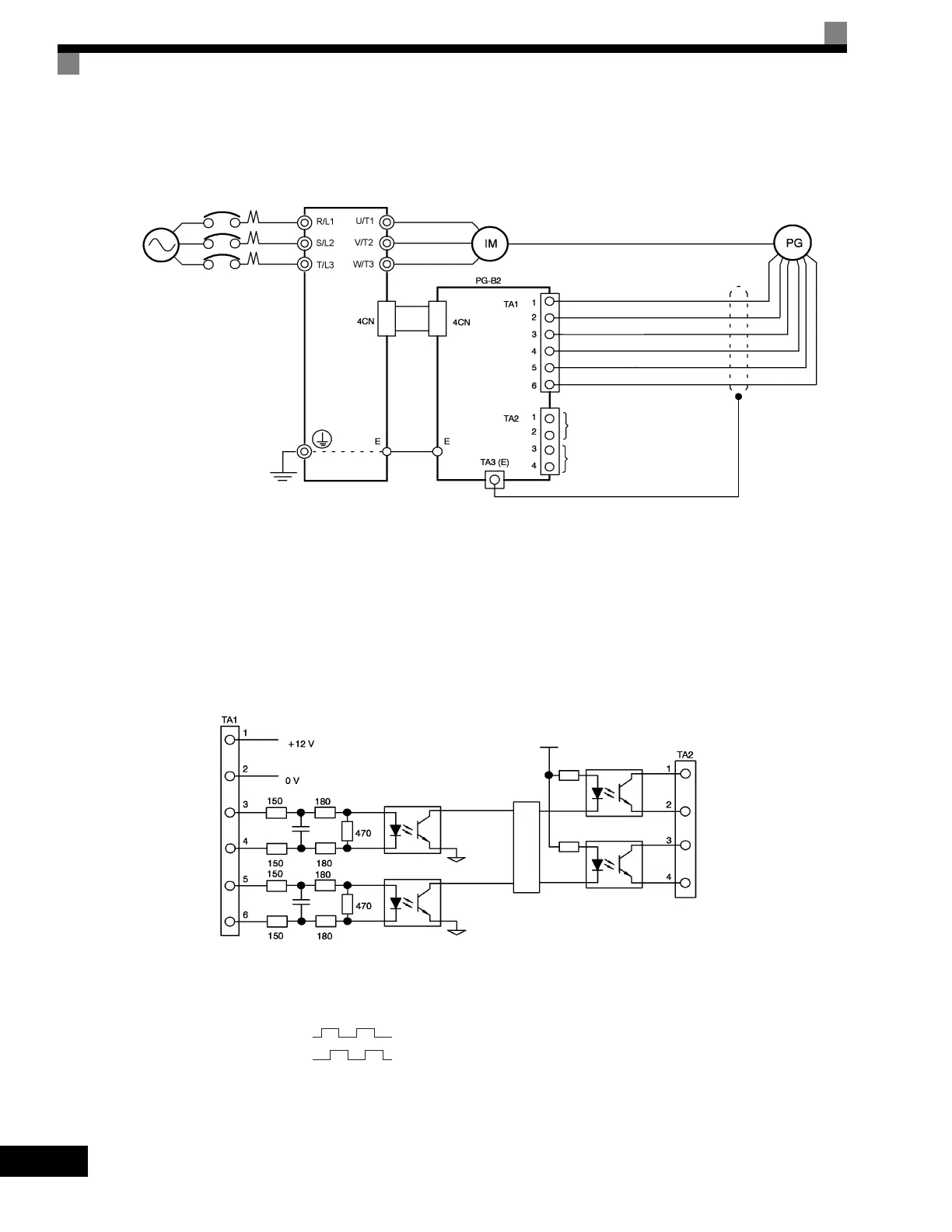
Wiring examples are provided in the following illustrations for the PG-B2.
• Shielded twisted-pair wires must be used for signal lines.
• Do not use the pulse generator's power supply for anything other than the pulse generator (encoder).
Using it for another purpose can cause malfunctions due to noise.
• The length of the pulse generator's wiring must not be more than 100 meters (328 ft).
• The direction of rotation of the PG can be set in user parameter F1-05. The factory preset if for forward
rotation, A-phase advancement.
Fig 2.22 PG-B2 Wiring
• When connecting to a voltage-output-type PG (encoder), select a PG that has an output impedance with
a current of at least 12 mA to the input circuit photocoupler (diode).
• The pulse monitor dividing ratio can be changed using parameter F1-06.
Fig 2.23 I/O Circuit Configuration of the PG-B2
Three-phase
200-240 Vac
(380-480 Vac)
Drive
Power supply +12 Vdc
Power supply 0 Vdc
A-phase pulse output (+)
A-phase pulse output (-)
B-phase pulse output (+)
B-phase pulse output (-)
A-phase pulse monitor output
B-phase pulse monitor output
PG power
supply +12
Vdc
A-phase pulse
input
B-phase pulse
input
A-phase
pulses
B-phase
pulses
Division rate circuit
B-phase pulse
monitor output
A-phase pulse
monitor output
A-phase pulses
B-phase pulses
Artisan Technology Group - Quality Instrumentation ... Guaranteed | (888) 88-SOURCE | www.artisantg.com

 Loading...


