Installing and Wiring Option Cards
2-39
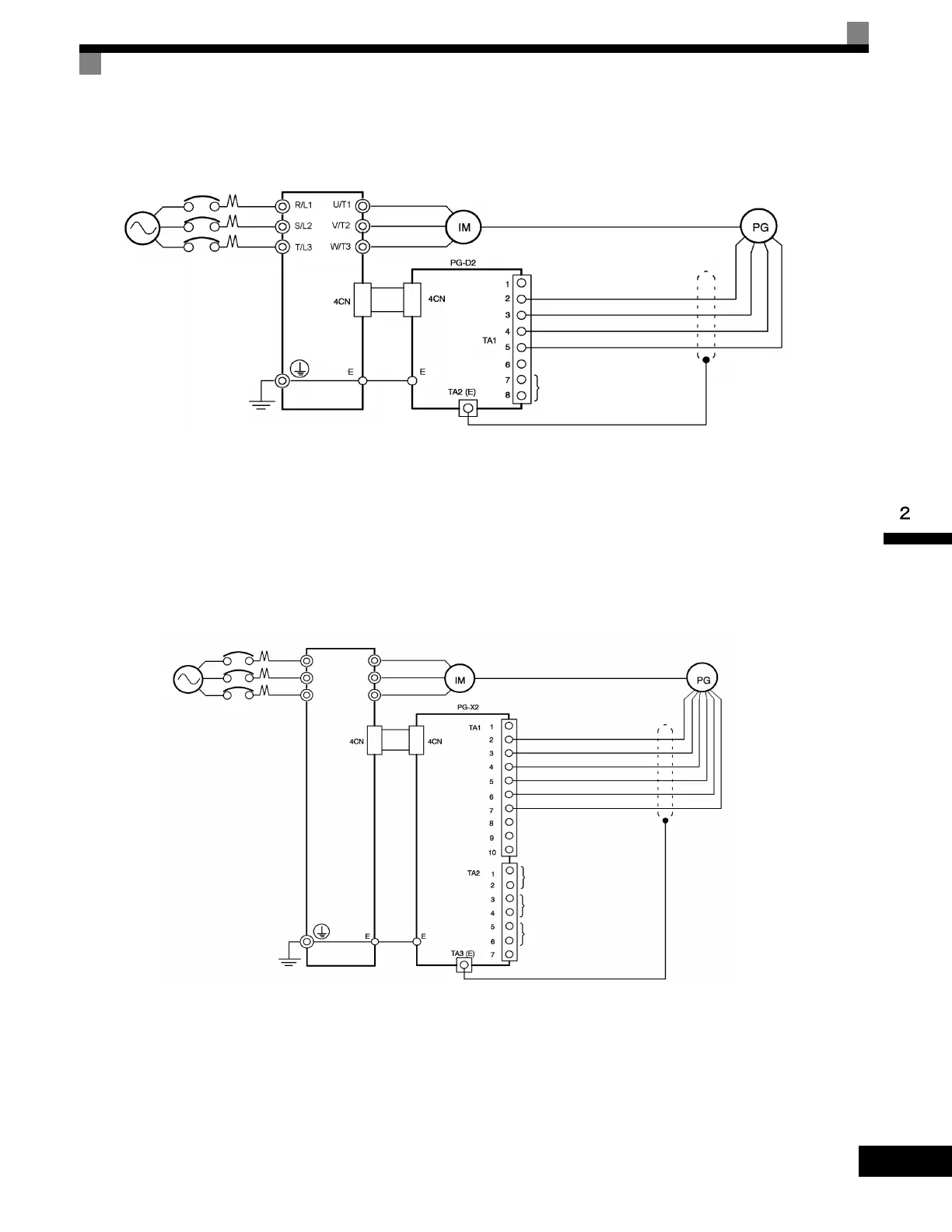
Wiring the PG-D2
Wiring examples are provided in the following illustrations for the PG-D2.
• Shielded twisted-pair wires must be used for signal lines.
• Do not use the pulse generator's power supply for anything other than the pulse generator (encoder).
Using it for another purpose can cause malfunctions due to noise.
• The length of the pulse generator's wiring must not be more than 100 meters.
Fig 2.24 PG-D2 Wiring
Wiring the PG-X2
Wiring examples are provided in the following illustrations for the PG-X2.
• Shielded twisted-pair wires must be used for signal lines.
• Do not use the pulse generator's power supply for anything other than the pulse generator (encoder).
Using it for another purpose can cause malfunctions due to noise.
• The length of the pulse generator's wiring must not be more than 100 meters (328 ft).
• The direction of rotation of the PG can be set in user parameter F1-05 (PG Rotation). The factory preset
if for motor forward rotation, A-phase advancement.
Fig 2.25 PG-X2 Wiring
Three-phase
200-240 Vac
(380-480 Vac)
Drive
Power supply +12 Vdc
Power supply 0 Vdc
Power supply +5 Vdc
Pulse input + (A/B phase)
Pulse input - (A/B phase)
Pulse monitor output
Three-phase
200-240 Vac
(380-480 Vac)
Drive
Power supply +12 Vdc
Power supply 0 Vdc
Power supply +5 Vdc
A-phase pulse input (+)
A-phase pulse input (-)
B-phase pulse input (+)
B-phase pulse input (-)
A-phase pulse monitor output
B-phase pulse monitor output
Z-phase pulse monitor output
R/L1
S/L2
U/T1
V/T2
W/T3T/L3
Artisan Technology Group - Quality Instrumentation ... Guaranteed | (888) 88-SOURCE | www.artisantg.com

 Loading...


