Command Reference
INPUT_CASE
Table explanation
Group Program Flow Control
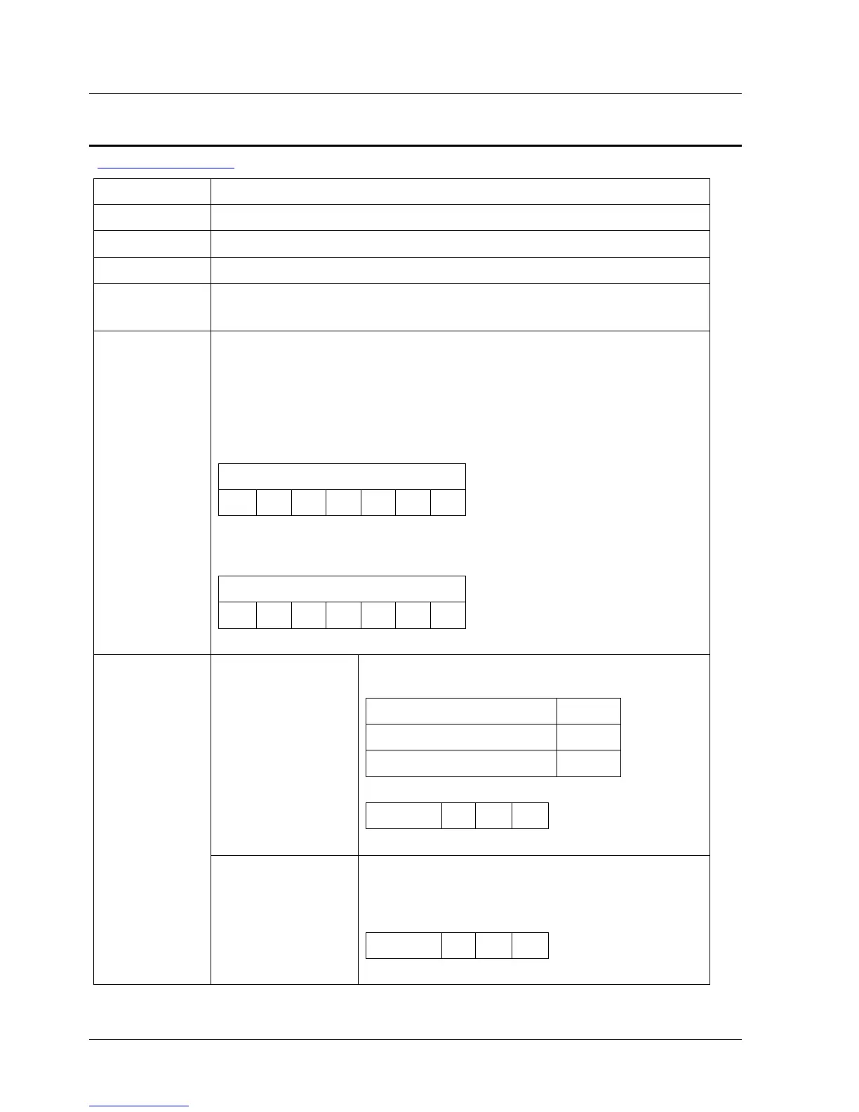
Syntax INPUT_CASE <input mask> <input state>
Op. Code 97
Modes Program
Range <input mask> – 1 to 0x00FFFFFF
<input state> – 0 to 0x00FFFFFF
Description The program flow is conditional on the state of a combination of
digital inputs. If the condition is True, the next program line is
executed. Otherwise, the next program line is skipped.
<input mask> is used to define which inputs are detected and
which are ignored (1 - detected, 0 - ignored). For example, if
<input mask> is set to 5 (in binary: 0101) only inputs 0 and 2 are
checked; the rest are ignored.
Input Mask
… 0 0 0 1 0 1
<input state> defines the logical combination to be detected as
True. For example, if <input state> is set to 4 (in binary: 0100),
True means input 0 OFF, input 1 OFF, input 2 ON and input 3 OFF.
Input State
… 0 0 0 1 0 1
Input mask Input mask (decimal value). Defines which
inputs are detected and which are ignored:
Setting Code
Ignore the input 0
Check the input 1
Serial 4 U V
Syntax
Arguments
Input state Input State (decimal value). A bit string
represents the digital input state. The leftmost
is input 0 related to pin 40 on CN1, etc. The
eighth bit is not in use.
Serial 4 U V
XtraWare User Manual 127