Parameter Reference
Note:
When working in YASKAWA Option Board Mode, all input and
output assignments are available. When working in modes C
and D, consult Table 27: Input and Output Availability per
Mode for a list of input and output signals that can be
assigned.
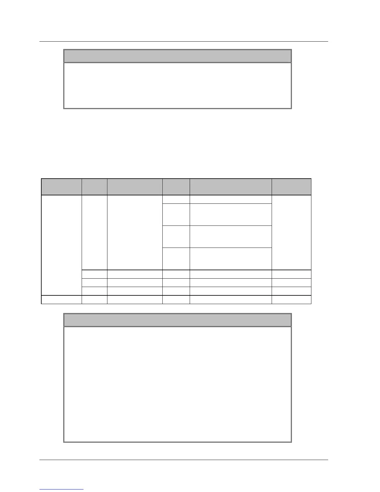
8.8. Table 26: Extended Output Signal
Selection
The outputs listed in the table below are used in the user program.
Table 26: Extended Output Signal Selection
Parameter Digit
Place
Name Settin
g
Description Default
Setting
0 Disabled.
1 Outputs from the SO1
(CN1-25, 26) output
terminal
2 Outputs from the SO2
(CN1-27, 28) output
terminal
0 QUICK_OUTPUT
Signal Mapping
3 Outputs from the SO3
(CN1-29, 30) output
terminal
0:disable
1 Not used - - 0
2 Not used - - 0
Pn2D2
3 Not used - - 0
Notes:
1. When more than one signal is allocated to the same output
circuit, data is output using OR logic.
2. Depending on the control mode, undetected signals are
treated as OFF. For example, in the speed control mode, the
/COIN signal is treated as OFF.
3. Types of /WARN signals: Overload and regenerative
overload.
4. When working in YASKAWA Option Board Mode, all input
and output assignments are available. When working in modes
C and D, consult Table 27: Input and Output Availability per
Mode for a list of input and output signals that can be
assigned.
XtraWare User Manual 231