Maximum Load Current Cooling Ability Overload Characteristics
Continuous
60 s
Motor Speed (%)
Torque (%)
150
10 33 100
120
100
80
50
0.0
Motor is designed to produce 100%
torque at base speed. Built with
effective cooling capabilities.
Reaching 100% when operating at
below the base frequency causes a
motor overload fault (oL1). The drive
fault output closes and the motor coasts
to stop.
n
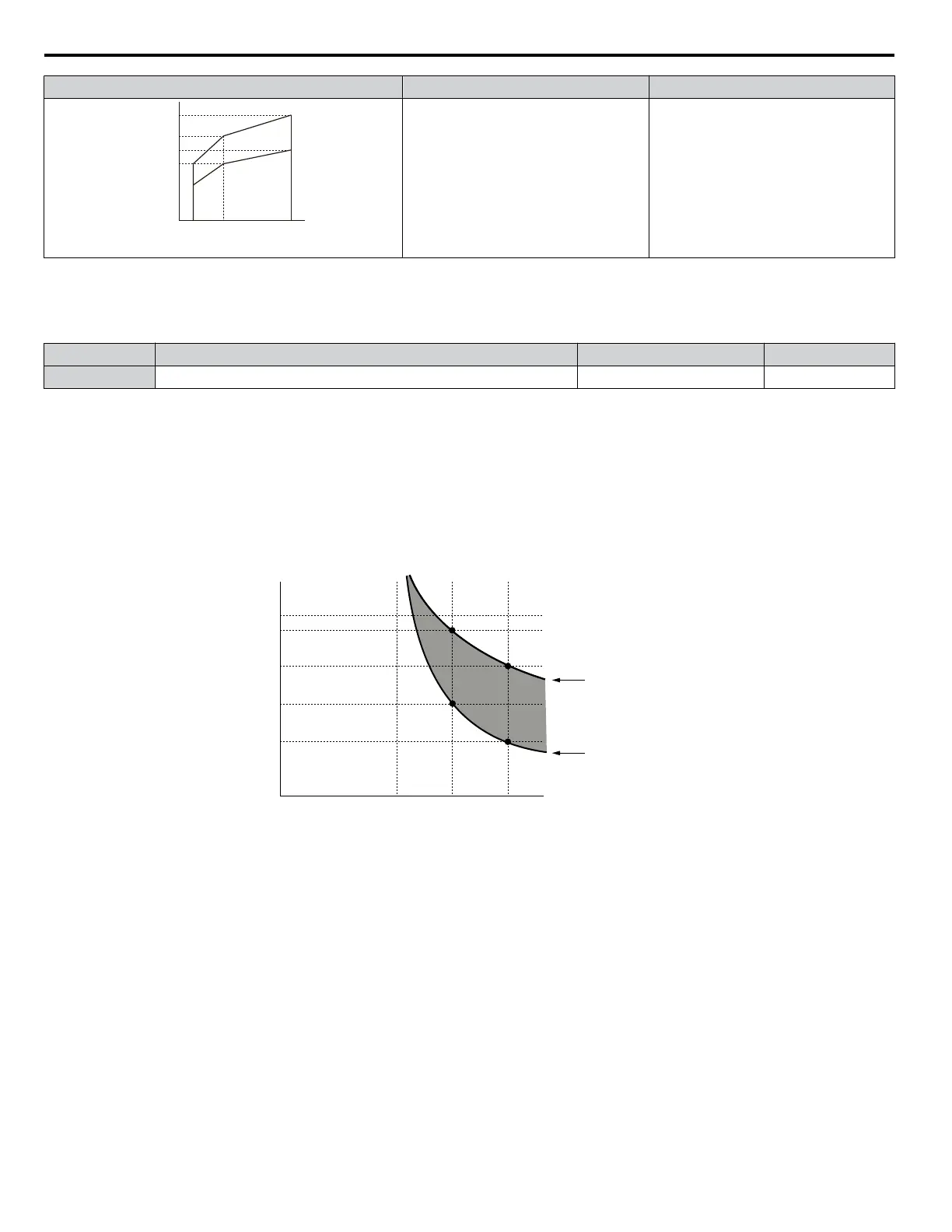
L1-02: Motor Overload Protection Time
Sets the detection time of motor overheat due to overload. This setting rarely requires adjustment, but should correlate with
the motor maximum load current protection time for performing a hot start.
No. Name Setting Range Default
L1-02 Motor Overload Protection Time 0.1 to 50.0 minutes 1.0 minute
Defaulted to operate with an allowance of 150% overload operation for one minute in a hot start.
Figure 1.58 illustrates an example of the electrothermal protection operation time using a general-purpose motor operating at
the value of E1-06, Motor Base Speed, with L1-02 set to one minute.
During normal operation, motor overload protection operates in the area between a cold start and a hot start.
• Cold start: Motor protection operation time in response to an overload situation that was suddenly reached when starting a
stationary motor.
• Hot start: Motor protection operation time in response to an overload situation that occurred during sustained operation at
rated current.
Operation time (minutes)
Cold start
Hot start
Motor current (%)
E2-01 = 100% motor current
10
7
3
1
0.4
0.1
0 100 150 200
Figure 1.58 Motor Protection Operation Time
n
Motor Protection Using a Positive Temperature Coefficient (PTC) Thermistor
Connect a motor PTC to an analog input of the drive for motor overheat protection.
When the PTC input signal reaches the motor overheat alarm level, an oH3 alarm will be triggered and the drive will continue
operation as selected in L1-03. When the PTC input signal reaches the overheat fault level, an oH4 fault will be triggered, a
fault signal will be output, and the drive will stop the motor using the stopping method determined in L1-04.
Figure 1.59 shows a PTC connection example for analog input A2. When using analog input A2, be sure to set Jumper S1 on
the control board for voltage input when using this function.
1.8 L: Protection Functions
100
YASKAWA SIEP YAIZ1U 03B YASKAWA AC Drive – Z1000 Programming Manual

 Loading...


