u
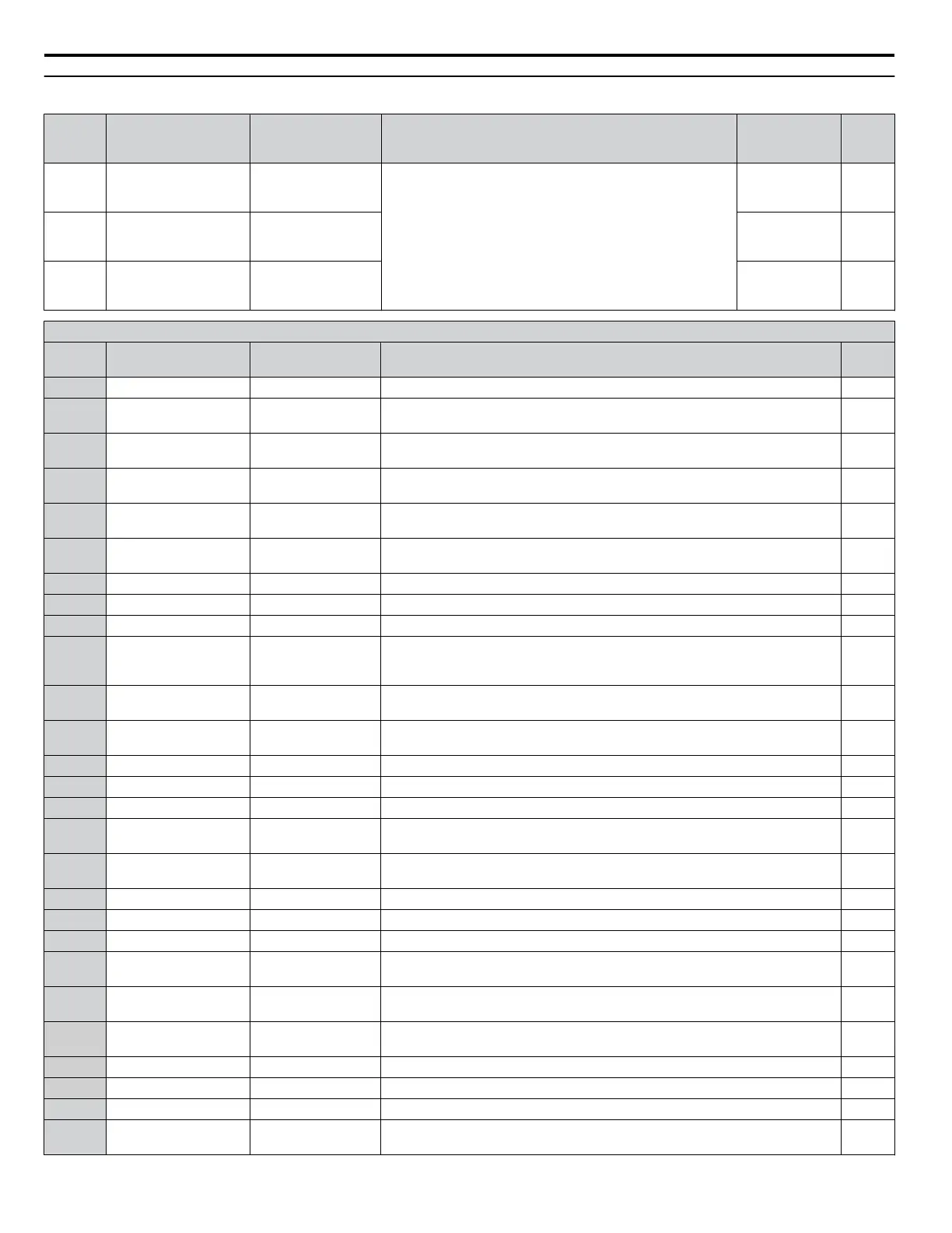
H2: Multi-Function Digital Outputs
No.
(Addr.
Hex)
Name LCD Display Description Values Page
H2-01
(40B)
Terminal M1-M2
function selection
(relay)
M1-M2 Func Sel
Refer to H2 Multi-Function Digital Output Settings on pages
208 to 209 for descriptions of setting values.
Default: 0
Range: 0 to 1B2
82
H2-02
(40C)
Terminal M3-M4
function selection
(relay)
M3/M4 Func Sel
Default: 1
Range: 0 to 1B2
82
H2-03
(40D)
Terminal M5-M6
function selection
(relay)
M5/M6 Func Sel
Default: 2
Range: 0 to 1B2
82
H2 Multi-Function Digital Output Settings
H2-oo
Setting
Function LCD Display Description Page
0 During run During RUN 1 Closed: A Run command is active or voltage is output. 83
1 Zero speed Zero Speed
Open: Output frequency is above the minimum output frequency set in E1-09.
Closed: Output frequency is below the minimum output frequency set in E1-09.
83
2 Speed agree 1 Fref/Fout Agree1
Closed: Output frequency equals the speed reference (plus or minus the hysteresis
set to L4-02).
84
3 User-set speed agree 1 Fref/Set Agree 1
Closed: Output frequency and speed reference equal L4-01 (plus or minus the
hysteresis set to L4-02).
84
4 Frequency detection 1 Freq Detect 1
Closed: Output frequency is less than or equal to the value in L4-01 with hysteresis
determined by L4-02.
84
5 Frequency detection 2 Freq Detect 2
Closed: Output frequency is greater than or equal to the value in L4-01 with
hysteresis determined by L4-02.
85
6 Drive ready Drive Ready Closed: Power up is complete and the drive is ready to accept a Run command. 85
7 DC bus undervoltage DC Bus Undervolt Closed: DC bus voltage is below the Uv trip level set in L2-05. 86
8 During baseblock (N.O.) BaseBlk 1 Closed: Drive has entered the baseblock state (no output voltage). 86
9
Frequency reference
source
Ref Source
Open: External Reference 1 or 2 supplies the frequency reference (set in b1-01 or
b1-15).
Closed: HOA keypad supplies the frequency reference.
86
A Run command source Run Cmd Source
Open: External Reference 1 or 2 supplies the Run command (set in b1-02).
Closed: HOA keypad supplies the Run command.
86
B
Torque detection 1
(N.O.)
Trq Det 1 N.O.
Closed: An overtorque or undertorque situation has been detected.
86
C Frequency reference loss Loss of Ref Closed: Analog frequency reference has been lost. 86
E Fault Fault Closed: Fault occurred. 86
F Through mode Not Used Set this value when using the terminal in the pass-through mode. 86
10 Minor fault Minor Fault
Closed: An alarm has been triggered, or the IGBTs have reached 90% of their
expected life span.
86
11
Fault reset command
active
Reset Cmd Active
Closed: A command has been entered to clear a fault via the input terminals or
from the serial network.
87
12 Timer output Timer Output Closed: Timer output. 87
13 Speed agree 2 Fref/Fout Agree2 Closed: When drive output frequency equals the frequency reference ±L4-04. 87
14 User-set speed agree 2 Fref/Set Agree 2 Closed: When the drive output frequency is equal to the value in L4-03 ±L4-04. 87
15 Frequency detection 3 Freq Detect 3
Closed: When the drive output frequency is less than or equal to the value in L4-03
±L4-04.
88
16 Frequency detection 4 Freq Detect 4
Closed: When the output frequency is greater than or equal to the value in L4-03
±L4-04.
88
17
Torque detection 1
(N.C.)
Trq Det 1 N.C.
Open: Overtorque or undertorque has been detected.
86
1A During Reverse Reverse Dir Closed: Drive is running in the reverse direction. 86
1B During baseblock (N.C.) BaseBlk 2 Open: Drive has entered the baseblock state (no output voltage). 89
1E Restart enabled Dur Flt Restart Closed: An automatic restart is performed 89
1F
Motor overload alarm
(oL1)
Overload (OL1)
Closed: oL1 is at 90% of its trip point or greater. An oH3 situation also triggers
this alarm.
89
A.9 H Parameters: Multi-Function Terminals
208
YASKAWA SIEP YAIZ1U 03B YASKAWA AC Drive – Z1000 Programming Manual

 Loading...


