u
C6: Carrier Frequency
n
C6-02: Carrier Frequency Selection
Sets the switching frequency of the drive output transistors. Changes to the switching frequency lower audible noise and reduce
leakage current.
Note: Increasing the carrier frequency above the default value automatically lowers the drive current rating. Refer to Rated Current Depending
on Carrier Frequency on page 55.
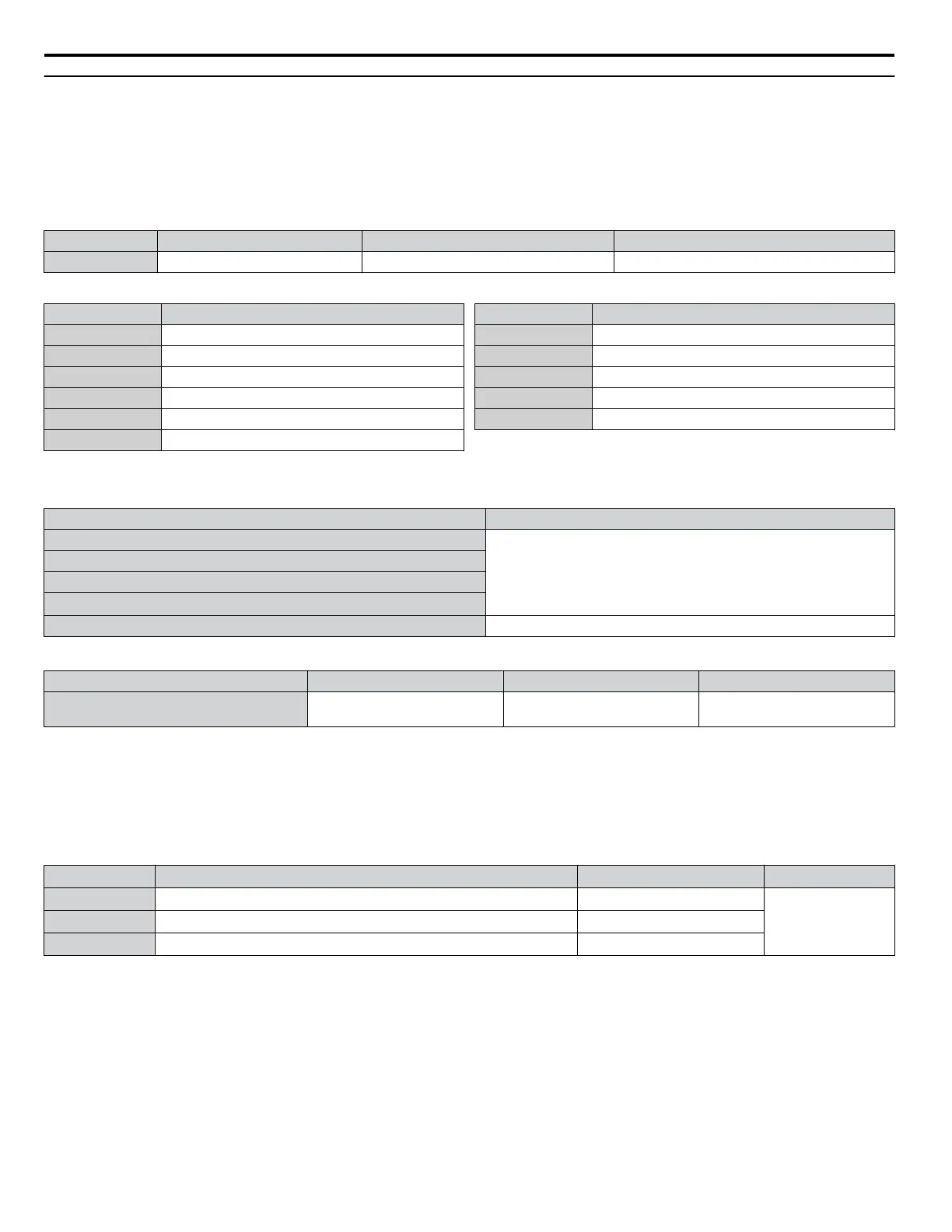
No. Parameter Name Setting Range Default
C6-02 Carrier Frequency Selection 1 to 5; 7 to 9; A to F Determined by A1-02 and o2-04
Settings:
C6-02 Carrier Frequency
1 2.0 kHz
2 5.0 kHz
3 8.0 kHz
4 10.0 kHz
5 12.5 kHz
7 Swing PWM 1
C6-02 Carrier Frequency
8 Swing PWM 2
9 Swing PWM 3
A Swing PWM 4
B to E No setting possible
F User defined
Note: Swing PWM uses a carrier frequency of 2.0 kHz as a base, then applies a special PWM pattern to reduce the audible noise.
Guidelines for Carrier Frequency Parameter Setup
Symptom Remedy
Speed and torque are unstable at low speeds
Lower the carrier frequency.
Noise from the drive affects peripheral devices
Excessive leakage current from the drive
Wiring between the drive and motor is too long
<1>
Audible motor noise is too loud Increase the carrier frequency or use Swing PWM.
<1> The carrier frequency may need to be lowered if the motor cable is too long. Refer to the following table.
Wiring Distance Up to 50 m Up to 100 m Greater than 100 m
Recommended setting value for C6-02 1 to F (up to 12.5 kHz)
1 to 2 (up to 5 kHz),
7 (Swing PWM)
1 (up to 2 kHz), 7 (Swing PWM)
Note: The maximum cable length is 100 m when using OLV/PM (A1-02 = 5).
n
C6-03, C6-04, C6-05: Carrier Frequency Upper Limit, Lower Limit, Proportional Gain
Note: C6-04 and C6-05 are available in V/f Control mode only.
These parameters set a user-defined or a variable carrier frequency. Set C6-02 to F to set the upper and lower limits and the
carrier frequency proportional gain.
No. Parameter Name Setting Range Default
C6-03 Carrier Frequency Upper Limit 1.0 to 12.5 kHz
Determined by
C6-02
C6-04 Carrier Frequency Lower Limit (V/f Control only) 1.0 to 12.5 kHz
C6-05 Carrier Frequency Proportional Gain (V/f Control only) 0 to 99
Setting a Fixed User-Defined Carrier Frequency
A carrier frequency between the fixed selectable values can be entered in parameter C6-03 when C6-02 is set to F.
In V/f Control, adjust parameter C6-04 to the same value as C6-03.
Setting a Variable Carrier Frequency (V/f Control)
In V/f Control, the carrier frequency can be set up to change linearly with the output frequency by setting the upper and lower
limits for the carrier frequency and the carrier frequency proportional gain (C6-03, C6-04, C6-05) as shown in Figure 1.22.
1.3 C: Tuning
54
YASKAWA SIEP YAIZ1U 03B YASKAWA AC Drive – Z1000 Programming Manual

 Loading...


