u
Writing to Multiple Registers
Function code 10H allows the user to write multiple drive MEMOBUS/Modbus registers with one message. This process
works similar to reading registers, in that the address of the first register to be written and the data quantity are set in the
command message. The data to be written must be consecutive so that the register addresses are in order, starting from the
specified address in the command message. The data order must be high byte then lower byte.
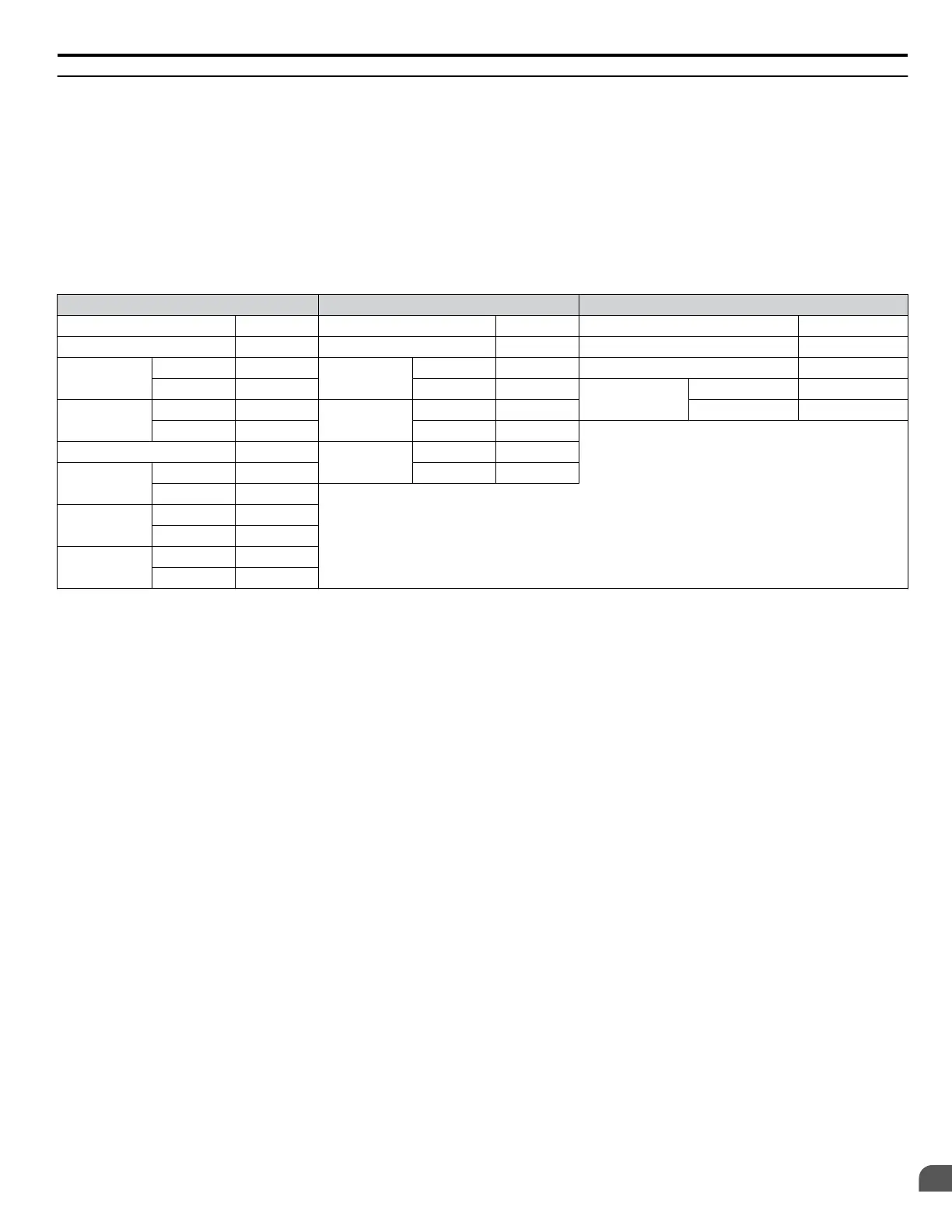
The following table shows an example of a message where a forward operation has been set with a frequency reference of
60.00 Hz for the slave 1 drive.
If parameter values are changed using the Write command, an Enter command may be necessary to activate or save the data
depending on the setting of H5-11. Refer to H5-11: Communications Enter Function Selection on page 252 and Refer to
Enter Command on page 261 for detailed descriptions.
Command Message Response Message (normal) Response Message (fault)
Slave Address 01H Slave Address 01H Slave Address 01H
Function Code 10H Function Code 10H Function Code 90H
Starting No.
Upper 00H
Starting No.
Upper 00H Error Code 02H
Lower 01H Lower 01H
CRC-16
Upper CDH
Data Quantity
Upper 00H
Data Quantity
Upper 00H Lower C1H
Lower 02H Lower 02H
Number of Bytes 04H
CRC-16
Upper 10H
Starting Data
Upper 00H Lower 08H
Lower 01H
Next Data
Upper 17H
Lower 70H
CRC-16
Upper 63H
Lower 39H
Note: Double the number of the data quantity for the number of bytes in the command message.
E.8 Message Examples
YASKAWA SIEP YAIZ1U 03B YASKAWA AC Drive – Z1000 Programming Manual
315
E
MEMOBUS/Modbus
Communications

 Loading...


