E.7 Message Format
u
Message Content
In MEMOBUS/Modbus communications, the master sends commands to the slave, and the slave responds. The message
format is configured for both sending and receiving as shown below, and the length of data packets depends on the command
(function) content.
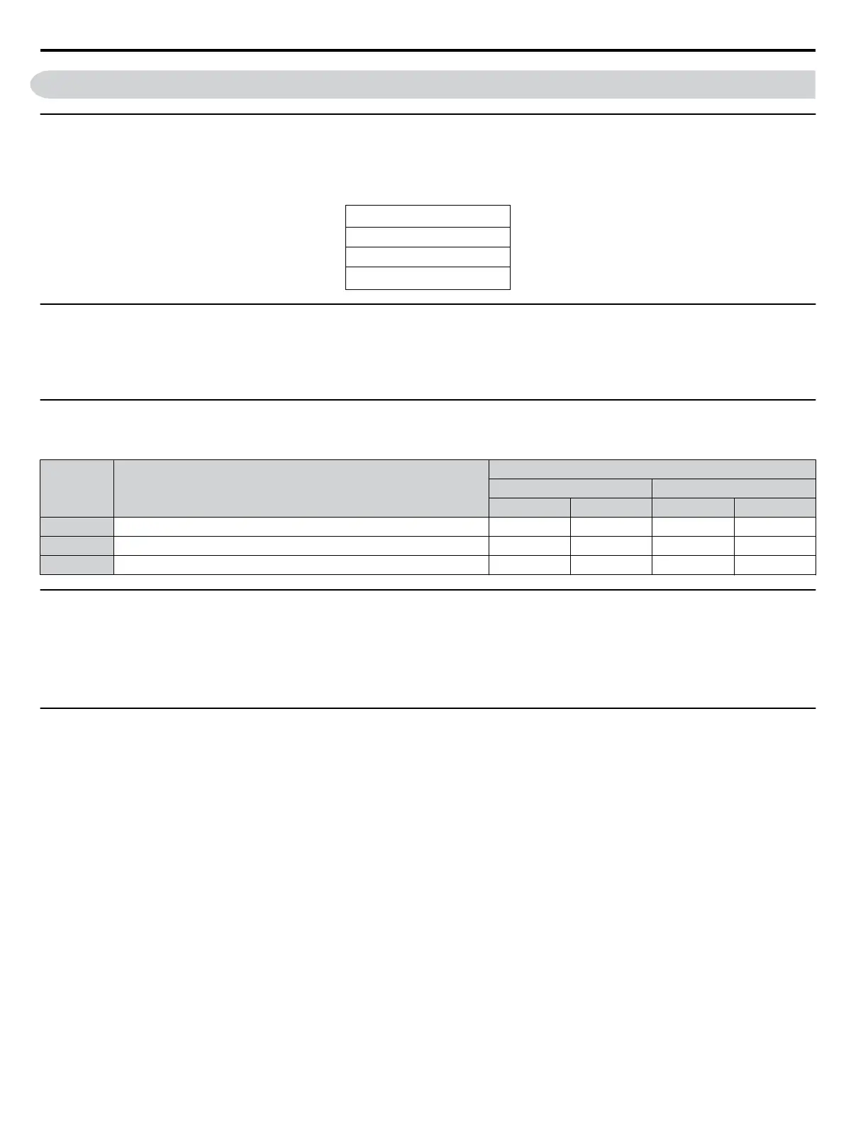
SLAVE ADDRESS
FUNCTION CODE
DATA
ERROR CHECK
u
Slave Address
The slave address in the message defines the note the message is sent to. Use addresses between 0 and FF (hex). If a message
with slave address 0 is sent (broadcast), the command from the master will be received by all slaves. The slaves do not provide
a response to a broadcast type message.
u
Function Code
The three types of function codes are shown in the table below.
Function
Code
Function Name
Data Length (bytes)
Command Message Response Message
Minimum Maximum Minimum Maximum
03H Read MEMOBUS/Modbus registers 8 8 7 37
08H Loopback test 8 8 8 8
10H Write to multiple MEMOBUS/Modbus registers 11 41 8 8
u
Data
Configure consecutive data by combining the MEMOBUS/Modbus register address (test code in case of a loopback test) and
the data the register contains. The data length changes depending on the command details.
A drive MEMOBUS/Modbus register always has a data length of two bytes. Data written into drive registers must also always
have a length of two bytes. Register data read out from the drive will always consist of two bytes.
u
Error Check
The drive uses a CRC-16 (cyclic redundancy check, checksum method) for checking data validity. Use the procedure described
below when calculating the CRC-16 checksum for command data or when verifying response data.
n
Command Data
When the drive receives data, it calculates the CRC-16 checksum from the data and compares it to the CRC-16 value received
within the message. Both must match before a command is processed.
An initial value of FFFFH (i.e., all 16 bits equal 1) must be used for CRC-16 calculations in the MEMOBUS/Modbus protocol.
Calculate the CRC-16 checksum using the following steps:
1.
The starting value is FFFFH.
2.
Perform an XOR operation of this value and the slave address.
3.
Right shift the result.
4.
When the overflow bit of the shift operation becomes 1, perform an XOR operation of the result from step 3 above
and the fix value A001H.
5.
Repeat steps 3 and 4 until eight shift operations have been performed.
6.
After eight shift operations, perform an XOR operation with the result and the next data in the message (function code,
register address, data). Continue with steps 3 to 5 until the last data has been processed.
7.
The result of the last shift or XOR operation is the checksum.
E.7 Message Format
312
YASKAWA SIEP YAIZ1U 03B YASKAWA AC Drive – Z1000 Programming Manual

 Loading...


