1.2 b: Application
u
b1: Operation Mode Selection
n
b1-01: Frequency Reference Selection for AUTO Mode
Selects the frequency reference source 1.
Note: If a Run command is input to the drive, but the frequency reference entered is 0 or below the minimum frequency, the AUTO or HAND
indicator LED on the HOA keypad will light and the OFF indicator will flash.
No. Parameter Name Setting Range Default
b1-01 Frequency Reference Selection for AUTO Mode 0 to 3 1
Setting 0: HOA Keypad
Using this setting, the frequency reference can be input by:
• switching between the multi-speed references from d1-01 to d1-04.
• entering the frequency reference on the operator keypad.
Setting 1: Terminals (Analog Input Terminals)
Using this setting, an analog frequency reference can be entered as a voltage or current signal from terminals A1 or A2.
Voltage Input
Voltage input can be used at any of the two analog input terminals. Make the settings as described in Table 1.5 for the input
used.
Table 1.5 Analog Input Settings for Frequency Reference Using Voltage Signals
Terminal Signal Level
Parameter Settings
Notes
Signal Level
Selection
Function Selection Gain Bias
A1
0 to 10 V
with Zero Limit
H3-01 = 0
H3-02 = 0
(Frequency Reference Bias)
H3-03 H3-04
Set Jumper S1 on the terminal
board to “V” for voltage input.
0 to 10 V
without Zero
Limit
H3-01 = 1
A2
0 to 10 V
with Zero Limit
H3-09 = 0
H3-10 = 0
(Frequency Reference Bias)
H3-11 H3-12
0 to 10 V
without Zero
Limit
H3-09 = 1
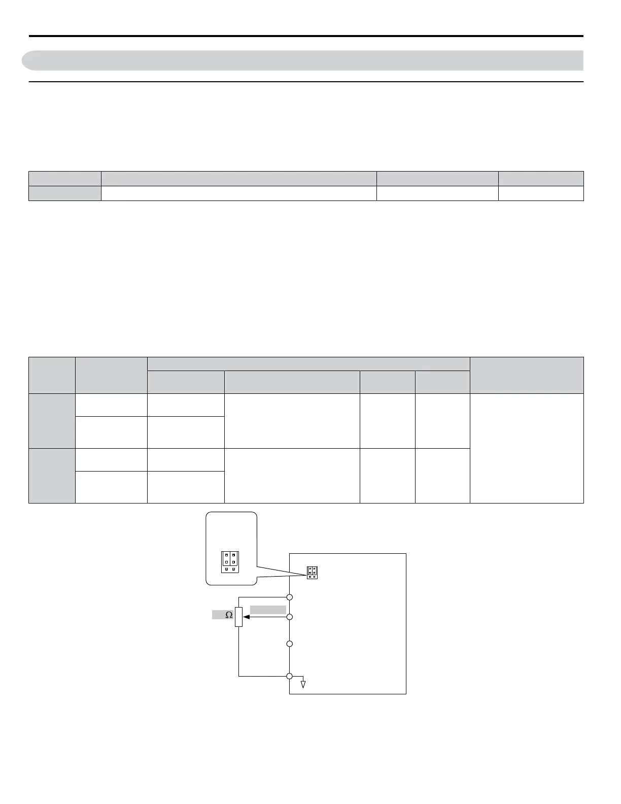
Drive
A1 Analog Input 1
0 to 10 V
AC Analog input common
2 k
+V
10.5 V, 20 mA power supply
A2 Analog Input 2
V
I
A1 A2
Jumper S1
Terminal A1/A2
Voltage/Current
Selection
V
I
A1 A2
Figure 1.1 Setting the Frequency Reference as a Voltage Signal at Terminal A1
Use the wiring example shown in Figure 1.1 for any other analog input terminals. When using input terminals A1 and A2,
make sure Jumper S1 is set for voltage input.
1.2 b: Application
24
YASKAWA SIEP YAIZ1U 03B YASKAWA AC Drive – Z1000 Programming Manual

 Loading...


