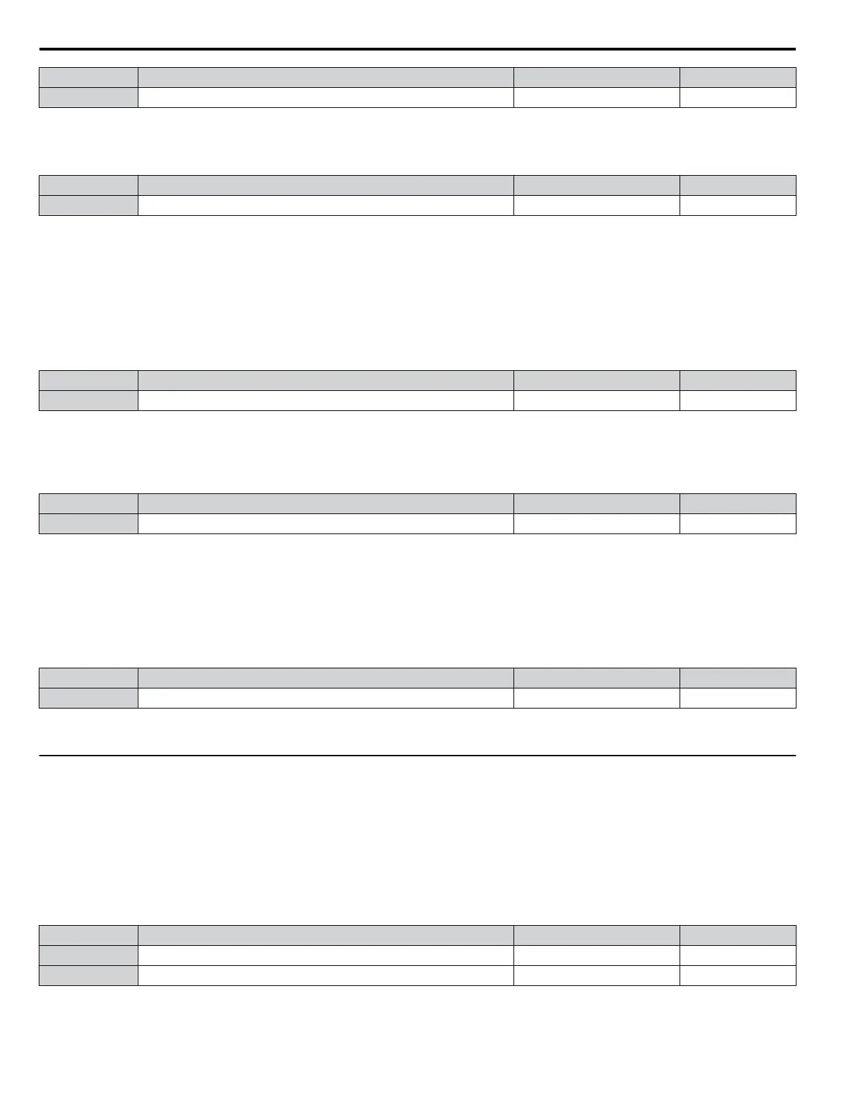
No. Name Setting Range Default
b3-19 Number of Speed Search Restarts 0 to 10 3
n
b3-24: Speed Search Method Selection
Sets the Speed Search method.
No. Parameter Name Setting Range Default
b3-24 Speed Search Method Selection 0, 1 0
Setting 0: Current Detection
Setting 1: Speed Estimation
Note: Refer to Current Detection Speed Search (b3-24 = 0) on page 31 and Refer to Speed Estimation Type Speed Search (b3-24 = 1) on page
32 for explanations of the Speed Search methods.
n
b3-25: Speed Search Wait Time
Sets the wait time between Speed Search restarts. Increase the wait time if problems occur with overcurrent, overvoltage, or
if the SEr fault occurs.
No. Name Setting Range Default
b3-25 Speed Search Wait Time 0.0 to 30.0 s 0.5 s
n
b3-27: Start Speed Search Select
Selects a condition to activate Speed Search Selection at Start (b3-01) or External Speed Search Command 1 or 2 from the
multi-function input.
No. Name Setting Range Default
b3-27 Start Speed Search Select 0, 1 0
Setting 0: Triggered when a Run Command Is Issued (Normal)
Setting 1: Triggered when an External Baseblock Is Released
n
b3-33: Speed Search Selection when Run Command is Given during Uv
Activates and deactivates Speed Search at start in accordance with whether a Run command was issued during an undervoltage
(Uv) condition. Function is active when a momentary power loss (L2-01 = 1 or 2), Speed Search at start (b3-01 = 1), and
coasting to a stop (b1-03 = 1) are enabled.
No. Name Setting Range Default
b3-33 Speed Search Selection when Run Command is Given during Uv 0, 1 0
Setting 0: Disabled
Setting 1: Enabled
u
b4: Timer Function
The timer function is independent of drive operation and can delay the switching of a digital output triggered by a digital input
signal and help eliminate chattering switch noise from sensors. An on-delay and off-delay can be set separately.
To enable the timer function, set a multi-function input to “Timer Function Input” (H1-oo = 18) and set a multi-function
output to “Timer output” (H2-oo = 12). Only one timer can be used.
n
b4-01, b4-02: Timer Function On-Delay, Off-Delay Time
b4-01 sets the on-delay time for switching the timer output. b4-02 sets the off-delay time for switching the timer output.
No. Name Setting Range Default
b4-01 Timer Function On-Delay Time 0.0 to 3000.0 s 0.0 s
b4-02 Timer Function Off-Delay Time 0.0 to 3000.0 s 0.0 s
1.2 b: Application
36
YASKAWA SIEP YAIZ1U 03B YASKAWA AC Drive – Z1000 Programming Manual

 Loading...


